This is a Pi-KVM GPIO implementation for ATX multiport support up to controlling 4 PC ports with the XH-HK4401 4-port HDMI USB KVM Switch and a custom breakoutboard for ATX switch. The project is based on Pi-KVM V2. If you are using Pi-KVM V3, you would need to make adaptations for GPIO pins based on the Pin Mapping and Reference sections.
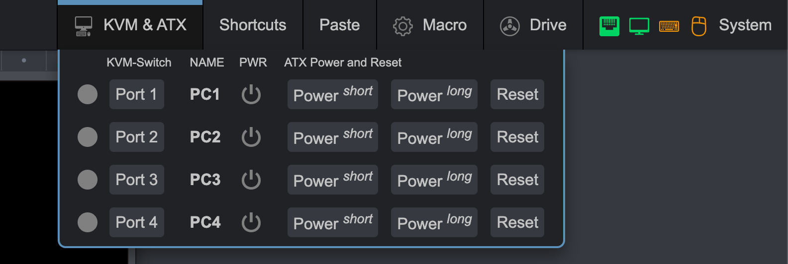
The implementation is accomplished through adding the addtional GPIO pins to the Pi-KVM Web GUI under /etc/kvmd/override.yaml.
Make sure you have the 3 hardwares to make the KVM switch work:
- Pi-KVM V2 with RPi 4B model (Pi-KVM V3 requires adaptations)
- A HDMI USB KVM Switch
- A Custom ATX Switch
Follow the guide to setup the hardware for HDMI USB KVM Switch. In this project's instance, the XH-HK4401 KVM Switch is used.
Set the Web GUI for ATX Switch using the following guide:
In the Pi-KVM terminal:
Obtain the root permission:
su -
Set to read-write mode:
rw
Go to the /boot directory:
cd /boot
Make backup of cmdline.txt:
cp cmdline.txt cmdline.txt.bak
Remove the console=serial0,115200 parameter from /boot/cmdline.txt:
nano cmdline.txt
Go to the /etc/kvmd directory:
cd /etc/kvmd
Make backup of override.yaml and web.css:
cp override.yaml override.yaml.bak
cp web.css web.css.bak
Copy override.yaml and web.css in this repo to your Pi-KVM OS, e.g., through SFTP or through nano to edit the files:
nano override.yaml
nano web.css
Set the OS back to read-only mode:
ro
Restart the kvmd service:
systemctl restart kvmd
Take a reference of the pin mapping for _PWRSW_, _RESET_, and _PLED_ from the Pi-KVM V2 guide to setup your own breakoutboard for ATX switch.

The following GPIO pins are used for controlling 4 PCs:
| PCs | _PWRSW_ Pin | _RESET_ Pin | _PLED_ Pin |
|---|---|---|---|
| PC1 | GPIO #23 | GPIO #27 | GPIO #24 |
| PC2 | GPIO #18 | GPIO #17 | GPIO #25 |
| PC3 | GPIO #16 | GPIO #19 | GPIO #13 |
| PC4 | GPIO #20 | GPIO #26 | GPIO #21 |
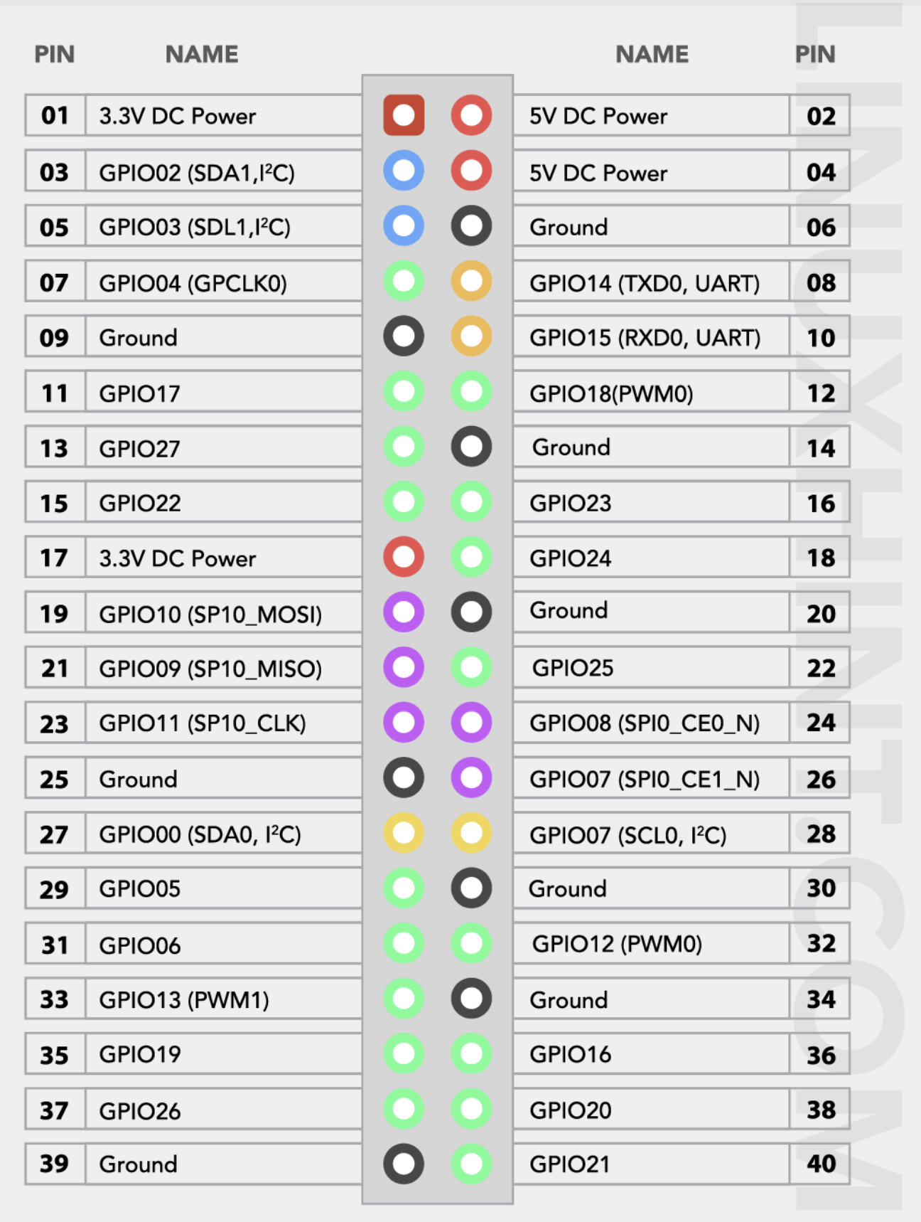
Source: https://linuxhint.com/gpio-pinout-raspberry-pi/
This reference is derived from the Pi-KVM V3 doc. However, this project is based on Pi-KVM V2; only take this as a reference to check the available GPIO pins and disable some pikvm service if needed.
GPIO pinout
Before proceeding, make sure that the mb you are using has normal ATX headers
- ATX control
power led = GPIO 24- Used for reading the host power state.hdd led = 22- Same for the HDD activity.power switch = 23- Used for pressing the power button of the host.reset switch = 27- Same for the reset button.
These pins can't be used for any other purposes even if ATX function is disabled.
-
I2C bus -
GPIO 2, 3- Can be used as I2C ONLY (OLED/RTC). -
1-Wire [19] -
GPIO 4- Also available under ATX RJ-45 port (point [19] on the above) as bi-directional buffered open-drain 5V for regular 1-Wire usage. -
UART -
GPIO 14, 15- Can be used as UART only for the serial console. When jumpers [5] are removed, you can connect to pins 14 and 15 directly using GPIO header. Also you can remove jumper [5] and disable UART console in the/boot/config.txtand/boot/cmdline.txtto use this pins for any purpose. But it's not recommended. -
Red activity led on the front [8] -
GPIO 13- Can be disabled in/boot/config.txtand available on the Neo-pixel port [19]. -
PWM fan controller -
GPIO 12. Can be used for custom purposes if the fan disconnected andkvmd-fanservice is stopped. -
I2S HDMI sound -
GPIO 18, 19, 20, 21. Can be used for custom purposes if thetc358743-audiooverlay in/boot/config.txtis disabled AND jumpers [4] are removed. -
USB breaker -
GPIO 5- Can't be used for any other purposes.
Due to the limitation with number of the available GPIO ports on Pi-KVM V2, HDD Leds are not available on the Web GUI. Following the Pin Mapping section, if you find out additional GPIO pins that can be used for PC2-PC4, feel free to let me know.
- The Pi-KVM project.
- zappanaut's pikvm-usb-atx-ctrl repo that inspired this project.