Ploopy Mouse Kit Assembly
Do not flash new firmware until you've verified that the electronics are all working.
That means, finish building the Mouse, plug it in, use the stock firmware for about five minutes. Verify the buttons are all clicking. Verify that the cursor is moving. Verify that the scroll wheel works. Unplug the Mouse, hold the "back" button, plug it in, let go of the "back" button, and verify that the Mouse is in "bootloader" mode (the cursor won't be moving).
Once you've verified that it all works, you're good to go flashing new firmware.

In this section, you'll go over how to build the Ploopy Mouse from the official Ploopy Mouse kit.
Note that some of these pictures were taken at different times, so they may show a bit of inconsistency in between steps.
During this assembly process, you will have to insert and drive screws. The screws are driven into plastic, and plastic is fairly soft.
The screws that are shipped with this kit grip plastic very firmly, which is good, but if the screws are driven too hard, they will cause the plastic to separate.
So, whenever you drive screws during this assembly, go slowly, and go gently. When you feel significant resistance, stop.

- A #1 Phillips head screwdriver (or similar; you're looking for quite a small screwdriver here)
- Soldering iron
- Solder
A hammer and a pair of pliers would be useful, but they are not absolutely necessary.
The Top and Body has support material that must be removed prior to assembly.
"Support material" is more hollow than the structural plastic. You'll have to remove it before you continue with the assembly.
Most of the time, it can be removed using your fingers. If you find a bit of support material is not coming off, use a pair of pliers or tweezers to remove it. Be careful not to damage the parts as you remove the support material.
Prepare the following components:
- Printed circuit board
- PMW-3360 chip
- PMW-3360 optic
The PMW-3360 chip will come in a small piece of foam. Go ahead and remove the chip from the foam now.

Before soldering:
- MAKE SURE THAT THE PMW-3360 IS ORIENTED CORRECTLY BEFORE YOU SOLDER IT! This is a really easy step to mess up, so CHECK IT TWICE!
- See the photo for clarification. Note the orientation of the text on the chip, as well as the pattern of dots on the chip. Also note the "1" on the printed circuit board.
- Once you are absolutely sure that you have oriented the PMW-3360 correctly, solder it down.
- The sensor must be flat down as far as it can possibly slide into the holes before soldering. Don't let it "float" while you're soldering the first pin down.
- There are two pieces of yellow tape covering sensitive parts of the sensor. They should be pretty obvious to see.
- Carefully remove the yellow tape using your fingers or a pair of tweezers.
- Try to do this in a dust-free environment.
- Check your solder joints during this step to ensure that they are good.

- Orient the optic correctly before insertion. It should NOT require any force to insert fully; if it does, remove it and check the orientation before trying again.
- This isn't necessary, but if you want, you can permanently attach the optic to the sensor. To do so, set your soldering iron's temperature to around 500F or 260C. Find the small posts that are poking through the PMW-3360 chip. Using the flat side of your soldering iron, squish them flat. You're trying to make them bow out (kind of like a mushroom) so that the optic stays in place.
- If you don't attach the optic to the sensor, it's not a big deal. It might pop out during the assembly, but once everything is assembled, it is held in place and won't move.

Prepare the following components:
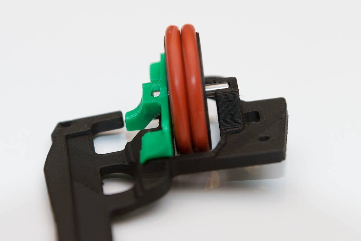
- Scroll Wheel
- Silicone O-ring x2
- 3mm x 18mm dowel rod

- Place the O-rings onto the Scroll Wheel. The O-rings are very strong and should not break during this step, even if you're quite rough with them.
- Check for stringing inside the Scroll Wheel's holes. "Stringing" is when a 3D-printer deposits extra, stringy plastic during a print. The holes have to be quite clear in order to function correctly. If you see any stringing inside the Scroll Wheel holes, use a toothpick or a pair of tweezers to scoop the excess plastic out.

Prepare the following components:
- Scroll Wheel Spring
- Assembled Scroll Wheel
- Internal Frame

- The Scroll Wheel Spring can be a bit tricky to install.
- To test out how it works, try inserting the Spring into the Internal Frame.
- The Spring inserts into the Internal Frame "sideways", rather than from the top. It shouldn't require excess force to insert, and should come back out easily.
- Once you understand how it's inserted into the Internal Frame, take it back out.

- Slide the Scroll Wheel into the Scroll Wheel Spring.
- Adjust the pin in the Scroll Wheel so that there is roughly a 1 to 2 millimetre distance between the Scroll Wheel Spring and the Scroll Wheel.
- The Scroll Wheel should not be rubbing against the Scroll Wheel Spring when the Wheel turns.
- This step can be tricky. Start by inserting the Scroll Wheel Spring into the Internal Frame; afterwards, "click" the other side of the Scroll Wheel's pin into the Internal Frame.
- The Scroll Wheel will look like it's closer to the Scroll Wheel Spring than to the Internal Frame. This is normal.
- Give the Scroll Wheel a spin. It shouldn't be rubbing against the Scroll Wheel Spring; if it is, adjust the Scroll Wheel's position on the metal dowel pin. You will probably have to remove the Scroll Wheel from the Internal Frame in order to do this.

Prepare the following components:
- Forward Button
- Back Button
- Side Button Frame
- Plastic screw x2

- Screw the Forward Button and the Back Button into the Side Button Frame.
- The Side Button Frame is delicate. Be careful as you screw everything together.

Prepare the following components:
- Base
- Assembled PCB
- Plastic screw x2
- Body

- Start by placing the PCB onto the Base.
- Slide the Body onto the Base.
- Nothing is currently holding the PCB down, so it might fall out.
Remember Step 0!

- If the PCB jostles around in the Body during this step, you can always move it back once the screws are inserted.

Prepare the following components:
- Assembled Side Buttons
- Assembled Scroll Wheel
- Assembled Body
- Right Mouse Buttons
- Plastic screw x3

- Line up the holes in the Internal Frame with the holes in the Base.
Remember Step 0!

- The screw goes through the Right Mouse Buttons, through the Internal Frame, and then into the Base.
- It may be a bit tricky to screw all three parts together at the same time, so take your time.
- Don't tighten this screw all the way down yet. We'll get to that in a bit. The screw should be tight enough to prevent the Right Mouse Buttons from lifting up, but you should still be able to freely twist the Internal Frame.
Remember Step 0!

- After you've lined up the Assembled Side Buttons with the Internal Frame, insert the front screw (as shown in the picture).
- Again, don't tighten this screw all the way down quite yet.

- This screw is a bit tricky to get in; you'll have to screw it in through a hole in the Body.
- Again, take your time and be patient.
- Note that, when properly installed, the "back" button will be slightly recessed into the body, and will not align with the "front" button. This is intentional.
Remember Step 0!
- Now that the Right Mouse Buttons and Side Buttons are installed, tighten the three screws that you just installed.
- Since the Top isn't yet on, this is a good opportunity to test the buttons.
- Give them all a click. The buttons should be crisp and clicky.
- Don't forget about the Side Buttons and the Middle Click.
Remember Step 0!


- Click the buttons on the Top. They should be good to go out of the box, but sometimes, they will require adjustment (typically upwards).
- If a button is sticking, gently grab it and pull upwards. GO VERY SLOWLY. The plastic probably won't break, but it's easy to bend it too far.
- Once you're happy with the click force for all the buttons and none of the buttons are sticking, you're all set.
Plug the Mouse into your computer. The buttons should be clicking, and if you move the Mouse, it should move the cursor.
Congrats, you finished building the Ploopy Mouse!
It's done! Love it, use it, but don't you dare abuse it!