Home
A solution for disabled persons accessibility to shops and buildings where presence of an operator is needed, could be this electronic project. Actually you can adapt same concept to many different issues, like being on call for your son, or being informed when your pet is coming back to home.
On Adafruit IoT online shop https://www.adafruit.com/category/342 you can buy main components to assemble the kit:
- one ADAFRUIT FEATHER M0 BLUEFRUIT LE https://www.adafruit.com/product/2995
- one ADAFRUIT LORA RADIO FEATHERWING - RFM95W https://www.adafruit.com/product/3231
- one ADAFRUIT FEATHER 32U4 RFM95 LORA RADIO https://www.adafruit.com/product/3078
Then you also need some other more common components:
- a push-button suitable to be applied on the 3D printed case, or any push-button you would like to use if your case is different
- a LED
- two 220 ohm resistors
- two 1 KΩ resistors
- a little push-button for PCB
- a piezo-speaker like this one https://www.sparkfun.com/products/11089
- a NPN transistor like 2N3904
- an 1p3t or 2p3t switch with four terminals like this one https://spanish.alibaba.com/product-detail/4-position-slide-switch-ss-23d03-321219961.html
- a vibration motor like https://www.sparkfun.com/products/8449
- a diode like 1N4001
- a few centimeters of Adafruit NeoPixel digital RGB LED strip https://www.adafruit.com/product/1376
- two Lithium Ion Batteries, like https://www.sparkfun.com/products/13854
The transmitter device is composed by two different modules (FEATHER M0 BLUEFRUIT LE and LORA RADIO FEATHERWING), which are overlapped one on each-other and connected together as in the picture.

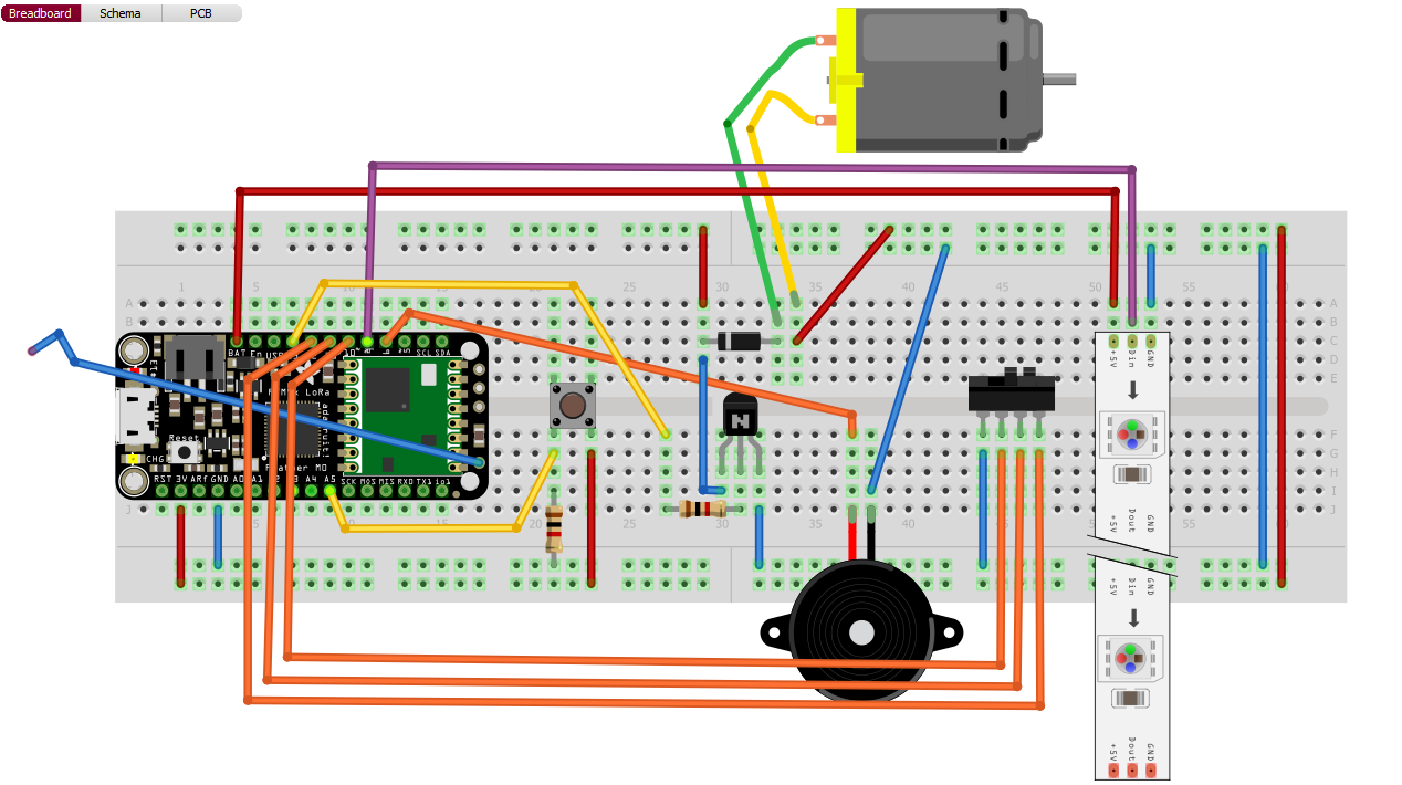
To learn how the circuit works and understand where to connect LED, resistors and button, look at following scheme. Blue and red wires on breadboard match with positive and negative poles of power source, usually a Li-Po rechargeable battery.
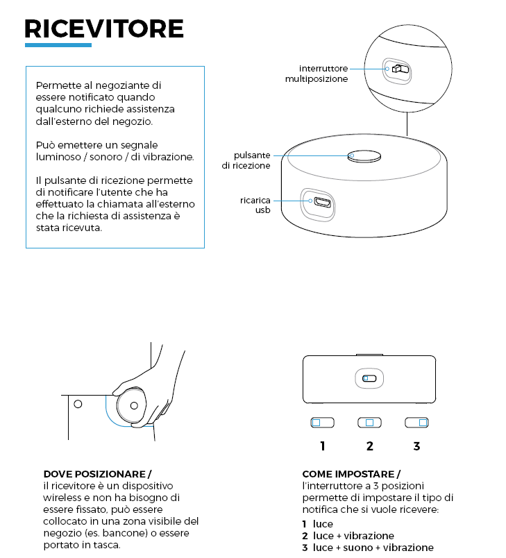
The receiver is the FEATHER 32U4 RFM95 LORA RADIO module you see in the picture, and you need to connect to it some more components, as the speaker, the switch, and an RGB LED strip.

As for transmitter you can follow circuit diagram to know where to solder wires.
You should now upload the code to your devices by USB cable. To do that follow these simple steps:
- Install Arduino IDE https://www.arduino.cc/en/Main/Software
- Set up Arduino IDE as explained here https://learn.adafruit.com/adafruit-feather-m0-radio-with-lora-radio-module/setup
- Possibly you have to install driver for Windows 7 as described here https://learn.adafruit.com/adafruit-feather-m0-radio-with-lora-radio-module/using-with-arduino-ide#install-drivers-windows-7-only
- Before uploading the Rampette code you should test your hardware by loading up a simple blinking code like this one:
// the setup function runs once when you press reset or power the board
void setup() {
  // initialize digital pin 13 as an output.
  pinMode(13, OUTPUT);
}
// the loop function runs over and over again forever
void loop() {
  digitalWrite(13, HIGH);   // turn the LED on (HIGH is the voltage level)
  delay(1000);              // wait for a second
  digitalWrite(13, LOW);    // turn the LED off by making the voltage LOW
  delay(1000);              // wait for a second
}
If the device LED blinks every second it means you can go on loading up the Rampette code.
There are obviously two codes to upload, one for each device.
The code to load up on the Transmitter is the following:
#include "Adafruit_BLE.h"
#include "Adafruit_BluefruitLE_SPI.h"
#include "Adafruit_BluefruitLE_UART.h"
#include "BluefruitConfig.h"

////////////////////////////////////////////
/////////////////CONNECTIONS////////////////
////////////////////////////////////////////

int buttonPin = 13;
int ledPin = 12;

////////////////////////////////////////////
/////////////////STATE_MACHINE//////////////
////////////////////////////////////////////

int state = 0;

////////////////////////////////////////////
////////////////LORA_DEVICE_ID//////////////
////////////////////////////////////////////

//const word ID = 61309;
//const word ID_RX = 61308;

//const word ID = 61311;
//const word ID_RX = 61310;

const word ID = 61313;
const word ID_RX = 613012;

////////////////////////////////////////////
/////////////////BLE_&_BEACON///////////////
////////////////////////////////////////////

#define BEACON_MAJOR               "0x0000"
#define BEACON_MINOR               "0x0002"
#define LOCAL_NAME                 "rampette"

int32_t charid_string;
int32_t charid_number;

Adafruit_BluefruitLE_SPI ble(BLUEFRUIT_SPI_CS, BLUEFRUIT_SPI_IRQ, BLUEFRUIT_SPI_RST);
boolean BLE_connected = false;

void setup() {
  pinMode(buttonPin, INPUT_PULLUP);
  pinMode(ledPin, OUTPUT);
  initradio();

  initBluetooth();
  setupBeacon();
  setupGatt();
  getGATTList();

  ble.reset(); //you ned to reset the ble after the configuration
  Serial.println();
}

void loop() {
  stateMachine();
  ble.update(200);
}

void stateMachine() {
  switch (state) {
    case 0: //nothing is happening
      analogWrite(ledPin, 0);

      if (checkbutton()) {
        state = 1;
        resetTimer();
        Serial.println("Going to state 1");
        //effettuo la chiamata
        sendData();
      }
      break;
    case 1:
      fadeLed();
      //aspetto conferma ricezione

      if (receiveData()) {
        state = 2;
        resetTimer();
        Serial.println("Going to state 2");
        writeCharacteristic(1, 2);
        readCharacteristic(1);
      } if (timeout()) {
        Serial.println("TIMEOUT: Going to state 0");
        writeCharacteristic(2, 0);
        state = 0;
      }

      break;
    case 2:
      digitalWrite(ledPin, HIGH);

//     this piece was introduced to try to read the value received by the app
//      readCharacteristic(2);
//      String returnMsg=readBleResponse();
//      Serial.println(">>>>>>>>>>");
//      Serial.println(returnMsg);
//      Serial.println("<<<<<<<<<<");
//
//      lookFor4(returnMsg);
//
      if (timeout()) {
        Serial.println("Going to state 0");
        state = 0;
        ble.reset();
      }
      break;
  }
}

void BLE_connected_callback(void) {
  Serial.println( "Connected to BLE");
  Serial.println( "Going to state 1...");
  //accendo il led
  digitalWrite(ledPin, HIGH);
  resetTimer();
  sendData();
  state = 1;
  BLE_connected = true;
}

void BLE_disconnected_callback(void) {
  Serial.println( F("Disconnected") );
  BLE_connected = false;
}
Remember to save in same folder also files from following list, which are needed to make code working:
- Adafruit_BLE.h https://github.com/frep/Arduino/blob/master/libraries/Adafruit_BluefruitLE_nRF51/Adafruit_BLE.h
- Adafruit_BluefruitLE_SPI.h https://github.com/adafruit/Adafruit_BluefruitLE_nRF51/blob/master/Adafruit_BluefruitLE_SPI.h
- Adafruit_BluefruitLE_UART.h https://github.com/adafruit/Adafruit_BluefruitLE_nRF51/blob/master/Adafruit_BluefruitLE_UART.h
- BluefruitConfig.h https://github.com/opencarecc/rampette/blob/master/chiamata/iteration2/trasmitter/breadboardProtoTrasmitter/BluefruitConfig.h
Now here is Receiver code:
#include <Adafruit_NeoPixel.h>
#include "NeoPatterns.h"
#include "notes.h"

////////////////////////////////////////////
/////////////////CONNECTIONS////////////////
////////////////////////////////////////////

#define BUTTON_PIN      A5
#define VIBRATION_PIN   13
#define MODE_A_PIN      10
#define MODE_B_PIN      11
#define MODE_C_PIN      12
#define SPEAKER_PIN     6

////////////////////////////////////////////
//////////////////NEO_PIXELS////////////////
////////////////////////////////////////////

#define PIXELRING_PIN   9
#define PIXELRING_COUNT 23

void ledComplete();
NeoPatterns leds (PIXELRING_COUNT, PIXELRING_PIN, NEO_GRB + NEO_KHZ400, & ledComplete);

uint32_t spento = leds.Color(0, 0, 0);
uint32_t bianco = leds.Color(255, 255, 255);
uint32_t blue = leds.Color(20, 20, 200);
uint32_t indigo = leds.Color(75, 0, 130);

////////////////////////////////////////////
////////////////LORA_DEVICE_ID//////////////
////////////////////////////////////////////

//const word ID = 61308;
//const word ID_RX = 61309;

//const word ID = 61310;
//const word ID_RX = 61311;

const word ID = 61312;
const word ID_RX = 61313;

////////////////////////////////////////////
/////////////////STATE_MACHINE//////////////
////////////////////////////////////////////

int state = 0;

////////////////////////////////////////////
////////////////RECEIVER_MODE///////////////
////////////////////////////////////////////

int mode = 0 ;
//0=light
//1=light+vibration
//2=light+vibration+sound

void setup() {
  pinMode(BUTTON_PIN, INPUT_PULLUP);

  pinMode(VIBRATION_PIN, OUTPUT);
  digitalWrite(VIBRATION_PIN, LOW);

  pinMode(MODE_A_PIN, INPUT_PULLUP);
  pinMode(MODE_B_PIN, INPUT_PULLUP);
  pinMode(MODE_C_PIN, INPUT_PULLUP);

  initradio();

  leds.begin();
  leds.SetFullColor(spento);
}

void loop() {
  leds.update();
  stateMachine();
  checkMode();
}

void stateMachine() {
  switch (state) {
    case 0:

      if (receiveData()) {
        state = 1;
        leds.Fade(bianco, spento, 20, 20, FORWARD); //start fade animation
        resetTimer();

      }
      break;

    case 1:
      if (mode == 2) {
        playMelody(); //play the melody
        vibrate();
      }
      else if (mode == 1) {
        vibrate();
      }

      //aspetto bottone
      if (checkbutton()) {
        //se premuto trasmetto sto arrivando
        leds.SetFullColor(spento);
        sendData();
        state = 0;
        resetMelody();
        stopVibration();
      }
       if (timeout()) {
        state = 0;
        leds.SetFullColor(spento);
        resetMelody();
        stopVibration();
      }
      break;
  }
}

void ledComplete() {
  leds.reverse();
}
Save in the folder these three files too:
- notes.h https://github.com/opencarecc/rampette/blob/master/chiamata/iteration2/receiver/breadboardProtoReceiver/notes.h
- NeoPatterns.h https://github.com/opencarecc/rampette/blob/master/chiamata/iteration2/receiver/breadboardProtoReceiver/NeoPatterns.h
- Adafruit_NeoPixel.h https://github.com/adafruit/Adafruit_NeoPixel/blob/master/Adafruit_NeoPixel.h
The team developed an App so that the user can see nearest shop with this service, and of course call for assistance. To install this software, made from framework Ionic (http://ionicframework.com), follow the guide here: https://github.com/opencarecc/rampette/tree/master/chiamata/iteration2/app
How the app works? Thanks to GPS you can see your position on the map, and also have a look at some icons around you. You notice that each icon corresponds to a specific type of business.
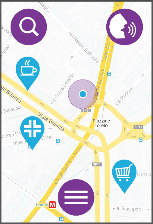
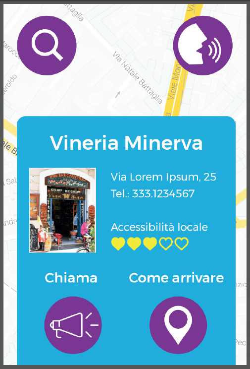
Clicking on the icons will bring you to the screen where to decide if calling them or reaching them.
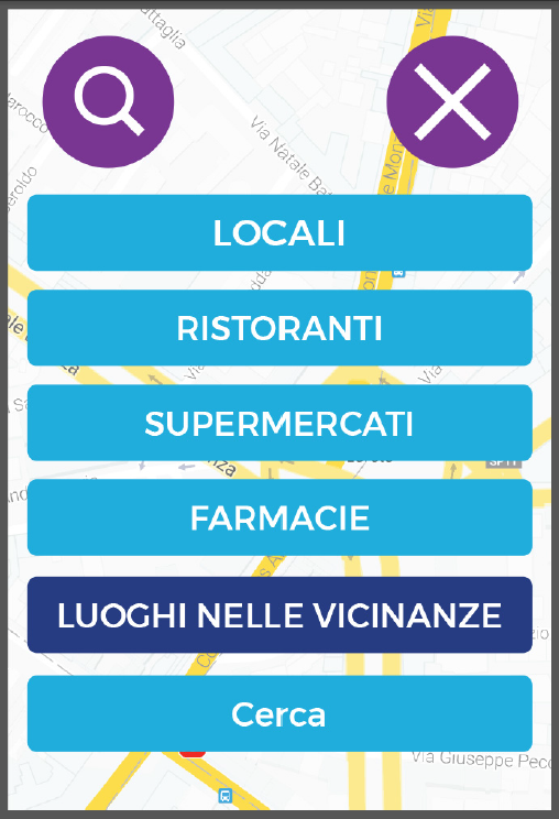
You also have opportunity to search among businesses of same type, clicking the lens icon on upper left, and making your choice here.
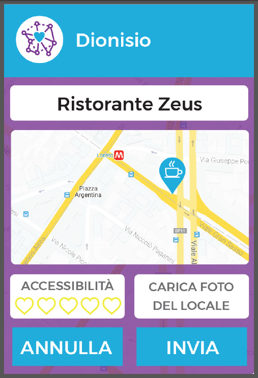
If you click the icon with three lines on the bottom of the first screen, you also can rate a store. Select the business from the list...
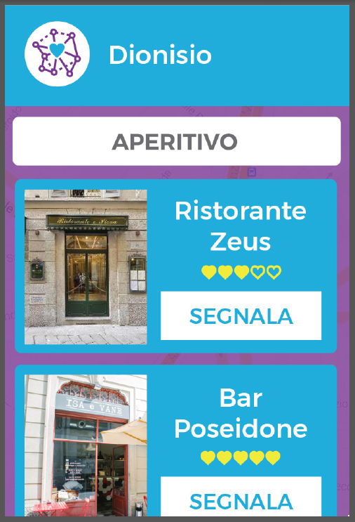
...and give your opinion about accessibility, then upload some pictures too.
We designed a pair of containers for both transmitter and receiver. You can easily print them if you have a 3D printer at home, otherwise you can ask a MakerSpace for help.
![]()
![]()
You can download .STL files for cases here:
- Transmitter: https://github.com/opencarecc/rampette/blob/master/chiamata/iteration2/trasmitter/3d%20model/transmitter.stl
- Receiver: https://github.com/opencarecc/rampette/blob/master/chiamata/iteration2/receiver/3d%20model/receiver.stl
3DM files from here:
- Transmitter: https://github.com/opencarecc/rampette/blob/master/chiamata/iteration2/trasmitter/3d%20model/transmitter.3dm
- Receiver: https://github.com/opencarecc/rampette/blob/master/chiamata/iteration2/receiver/3d%20model/receiver.3dm
You have also to cut from a 4 or 5 mm thick Plexiglas sheet the rear covers:
- Transmitter: https://github.com/opencarecc/rampette/blob/master/chiamata/iteration2/trasmitter/3d%20model/transmitter%20back.dxf
- Receiver: https://github.com/opencarecc/rampette/blob/master/chiamata/iteration2/receiver/3d%20model/receiver%20back.dxf
Use this image to print a sticker to be glued to both devices:

And this file: https://github.com/opencarecc/rampette/blob/master/comunicazione/sticker%20final.ai if you need to modify the graphic.
Once you had both cases printed, and you had made all connections, you can insert components and lock them in place before closing the backs. Look at pictures to see how the inside should appear.
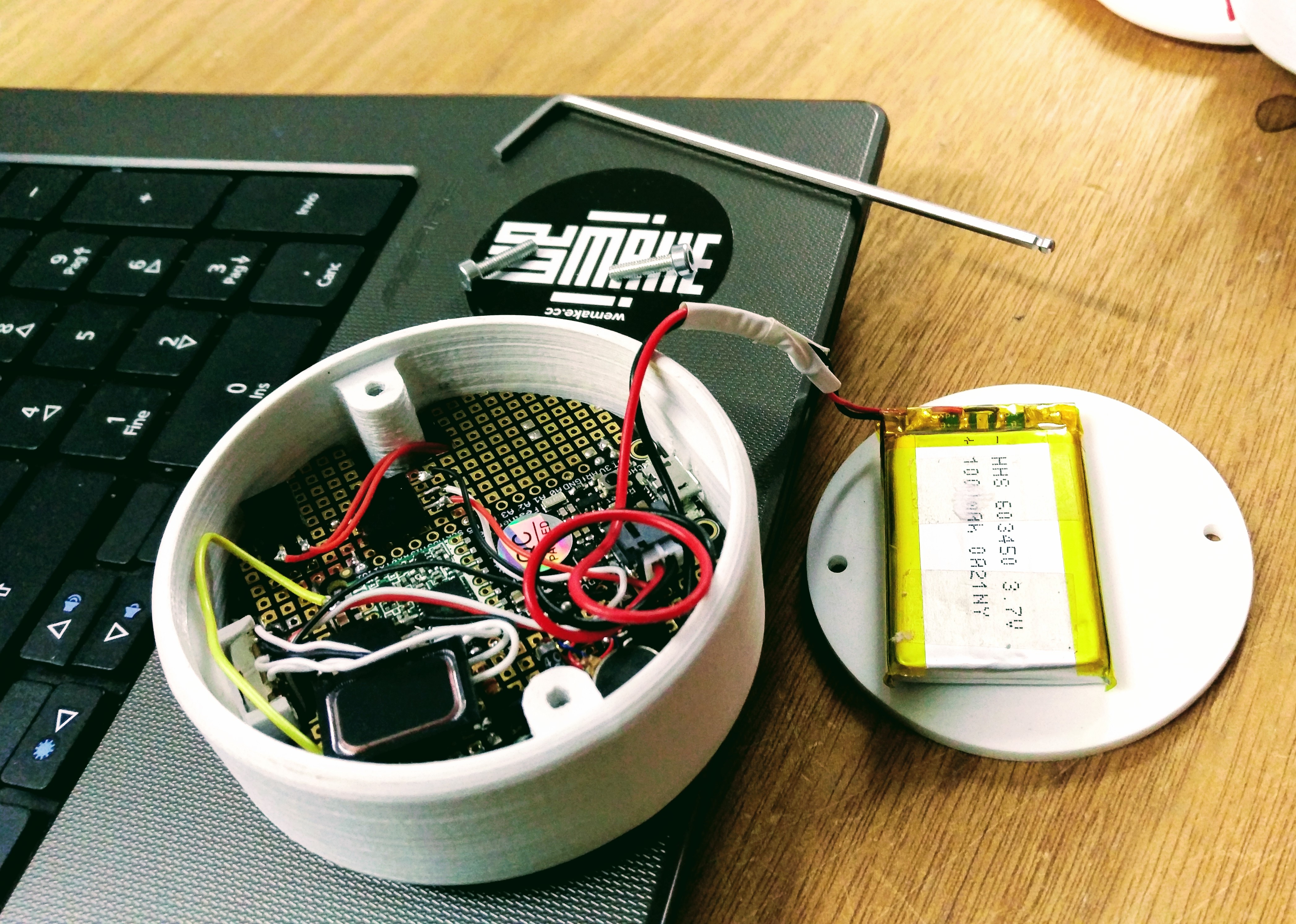
![]()
Secure back covers in position with two or three little bolts and an hex key.
![]()
Transmitter and receiver have very simple instructions, you probably don't either have to read them... anyway here they are. Remember that both devices can be charged by micro-USB socket.
Once you push the button, the light will show these two cases: it's a fixed light means that call is sent, it's a flashing light means the call has been received.
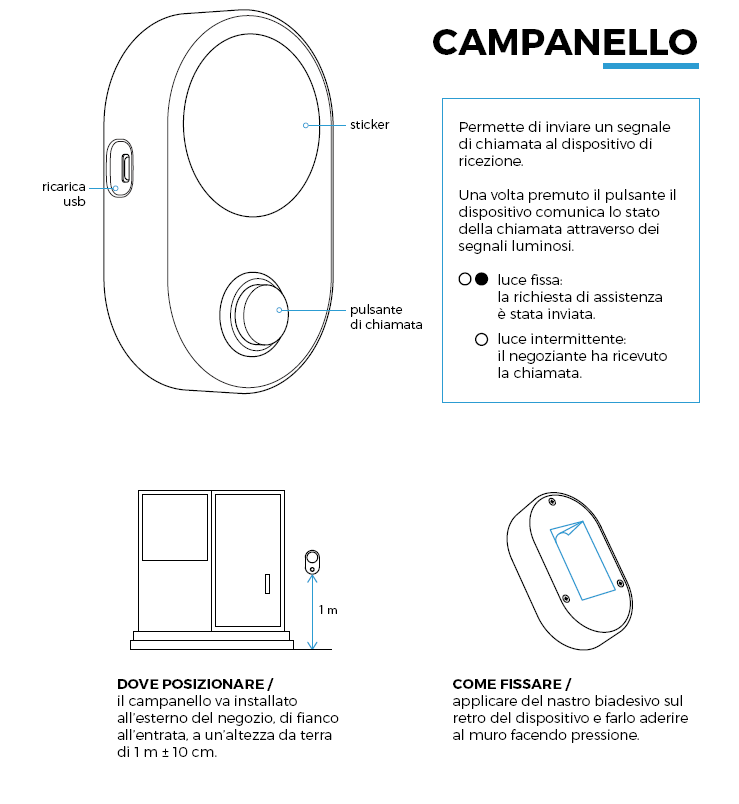
The receive also has a slide switch, which selects the following warning signals:
- only light
- light and vibration
- light vibration and ringtone
Your remote web-controlled technological IoT doorbell is now completed and ready to use. Let us know if you made it and how you would improve the project. And congrats to had achieved the bottom line of this tutorial.