This repository contains guides and source files to recreate an example project that applies an online update as described in the paper
Duc Do Tran, Kim Grüttner, Frank Oppenheimer, Wolfgang Nebel: Timing Contracts and Monitors for Safety Relevant Controller Design in IEC 61499 in proceedings of IEEE 25th International Conference on Emerging Technologies and Factory Automation (ETFA 2020), 08-11 September 2020, Vienna, Austria.
The IEC 61499 standard supports the design and deployment of distributed industrial control systems. It provides modularity through a hierarchical and event driven function block model and its deployment on distributed compute nodes. Even though IEC 61499 tools provide model based testing of applications before and after deployment, a systematic specification of timing requirements and its monitoring at design time is not well support. For safety relevant control applications the monitoring of execution time requirements at run-time would also serve an important safety measure. For this reason, we propose the application of assume/guarantee contracts on the ports of a function block. A hierarchical application of these contracts can be used to specify timing properties along causal event chains in IEC 61499 function bock models. Besides contract based specification and design time consistency checks we propose a new function block type, called Timing Contract Function Block (TCFB). It allows monitoring of a timing contract at design and run-time, when this TCFB gets deployed on the target hardware. We evaluate our proposed methodology and the application of TCFBs for monitoring of timed causality chains on a simple pick and place control system that is modeled in the open-source framework 4diac
To explain the proposed contract methodology, we present a simple example for the control system of a pick & place robot (PnP) in the production line that is modeled in 4diac, an open source IEC 61499 framework. Further details of the proposed timing contract methodology are described in our paper.
The industry is moving from centralized systems towards a more distributed paradigm. Large systems with a central intelligence controlling everything are transformed to distributed systems. In the distributed system, individual parts have intelligence and can communicate with each other smoothly, so the system acts as one whole. IEC 61499 defines a domain-specific modeling language for developing distributed industrial control solutions. IEC 61499 extends IEC 61131-3 by improving the encapsulation of software components for increased re-usability, providing a vendor independent format, and simplifying support for controller-to-controller communication. Its distribution functionality and the inherent support for dynamic reconfiguration provide the required infrastructure for Industry 4.0 and industrial IoT applications.
II. Eclipse 4diac (Framework for distributed industrial automation and control)
4diac provides two main components for developing and executing distributed control systems compliant to the IEC 61499 standard:
The 4diac-IDE is an integrated development environment written in Java, based on the Eclipse framework. It provides an extensible engineering environment for modeling distributed control applications compliant to the IEC 61499 standard. The 4diac IDE is used to create FBs, applications, configure the devices and other tasks related to IEC 61499. Within the 4diac IDE, applications, consisting of function blocks, can be deployed to devices running 4diac FORTE or other compliant run-time environments.
FORTE is a small portable C++ implementation of an IEC 61499 runtime environment which supports executing IEC 61499 FB networks on small embedded devices. 4diac FORTE typically runs on top of a (real-time) OS. 4diac FORTE is a multi-threaded and low memory-consuming runtime environment. It has been tested on several different operating systems, for example, Windows, Linux (i386, amd64, ppc, xScale, arm), NetOS, eCos, rcX from Hilscher, vxWorks, and freeRTOS.
In this work we have used the 4diac IDE Version 1.11.3 to create the IEC 61499 applications and some own function blocks (FBs), and these FBs will be used to describe the components and objects in the demo. We also used the 4diac FOTRE Version 1.11.3 to build the runtime environment for deploying our simulation and testing process. The details of the operating principles including the properties and features of event and data ports of our developed FBs are described as follow:
The PlantFB[Type: composite function block (CFB)]: is used to model the behavior of the PnP in our work. The FB is encapsulating a FB network (FBN) as show in following picture.
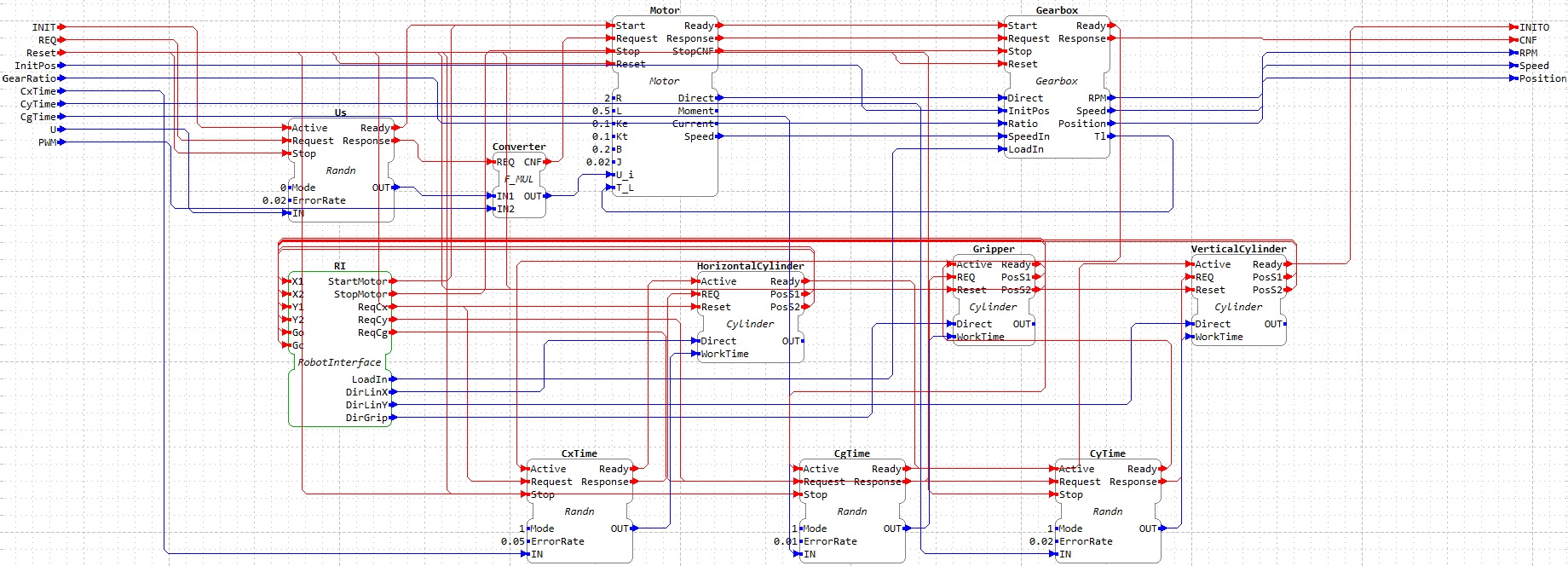 Its FBN includes:
Motor[Type: basic FB (BFB)]: is a model of a DC motor, represented by a mathematical model of the DC motor. This FB is combined with the Gearbox FB to generate rotational movement of the PnP robot.
-
Parameters: L,R,Ke,Kt, B, J are defined by REAL-type and represent the technical parameter of the DC motor.
-
Ui[Data type: REAL; Unit: V]: represents the input voltage of the motor.
-
T_L [REAL; Unit: Nm]: represent the torque of load, it effects on the shaft of the motor. In our PnP model, this value is get from the converted value of the Gearbox. Data type: REAL; Unit: Nm
-
Output data Moment[REAL; Unit: Nm] represents the rotational moment of the motor, Speed[REAL; Unit: rad/s] and RPM[REAL; presented unit: rad/s], this data represents the rotational speed of the motor.
-
Direct: (BOOL) is used to control the rotational direction of the Gearbox.
- If Ui < 0 then Direct -> 0 or FALSE
- If Ui ≥ 0 then Direct -> 1 or TRUE.
Gearbox[Type: BFB]: is used to model the functional behavior of a gearbox. It converts the load value, which is put on the shaft of the motor and gives the rotational speed, as well as the angle position of the robot.
-
Ratio [REAL]: is used to define the ratio value of the Gearbox.
-
Speed [REAL; Unit: rad/s]: represents the converted value of SpeedIn. It is calculated by: Speed = RatioSpeedIn*, this port is also linked to PlantFB to represent the rotational speed of the PnP robot.
-
RPM[REAL; Unit: round/min] represents the rotational speed in unit "round per minute" of the PnP robot. It is formally specified by RPM = Speed30/π*.
-
Tl [REAL; Unit: Nm]: represents the converted torque of the load as LoadIn, this value is connected to port Motor.T_L to model the load on the shaft of the motor. It is calculated by: Tl= RatioLoadIn*.
-
Position [REAL; Unit: ◦]: is linked to PlantFB.Position to feature the angle position of the PnP robot. It can be calculated as: Position(t) = Position(t0) + Speed180◦t/π. At the initialization time it is:Position(t0) = InitPos
-
Direct[BOOL]:
- If Direct -> 0 or FALSE: the angle position is determined in the counterclockwise rotation
- If Direct -> 1 or TRUE) : the angle position is determined in the clockwise rotation.
Cylinder[Type: BFB]: is used to create the linear movements along the horizontal and the vertical direction (controlled by the HorizontalCylinder and VerticalCylinder), as well as the pick and drop operation of the robot (controlled by Gripper).
-
WorkTime[REAL; Unit: s]: defines the working time (in second (s)) of the cylinder for the movement between two limited positions Pos1 and Pos2 .
-
Direct[BOOL]:
- If Direct -> 0 or FALSE: Whenever the REQ-event occurs, then the Pos1-event will occur after the time, which is defined or get at WorkTime.
- If Direct -> 1 or TRUE: Whenever the REQ-event occurs, then the Pos2-event will occur after the time, which is defined or get at WorkTime.
-
OUT[BOOL]: will be set to 1 (TRUE), when the cylinder is at Pos1 or Pos2, and it will be set to 0 (FALSE) for all other positions.
Randn[Type: BFB]: this type is built to generate a random real number used for model a random value of supply voltage (named Us), excution time of cylinders (named CxTime, CyTime and CgTime).
-
Mode[BOOL]
- If Mode -> 0 or FALSE, then OUT = IN*(1 ± ErrorRate)
- If Mode -> 1 or TRUE, then OUT = IN*± ErrorRate
-
IN[REAL]: a constant value.
-
OUT[REAL]: random value.
RobotInterface[Type: Adapter]: we also created an adapter RobotInterface named RI to reduce the number of connections between PlantFB and ControllerFB. This FB transmits the sensor signals of cylinders from PlantFB to ControllerFB inlude X1/X2, Y1/Y2 and Go/Gc w.r.t. cylinders HorizontalCylinder, VerticalCylinder and Gripper. It also gives the request signals from ControllerFB to PlantFB including StartMotor, StopMotor to start and stop the motor; ReqCx (is associated with DirLinX), ReqCy (is associated with DirLinY) and ReqGrip (is associated with DirGrip) to operate the cylinder HorizontalCylinder, VerticalCylinder and Gripper respectively. Furthermore, this FB sends the measured value of load to the LoadIn port of the Gearbox.
F_MUL: we use this FB to convert the controlled value from ControllerFB (PWM) into the supply voltage for the motor. It is picked up from the standard library of 4diac. The control value is calculated by multiplication between the value at Us.Out and the value at PlantFB.PWM
We develop the ControllerFB[Type: BFB] to meet the desired behaviors and properties of the manufacturing process as described in our paper (see figure below).
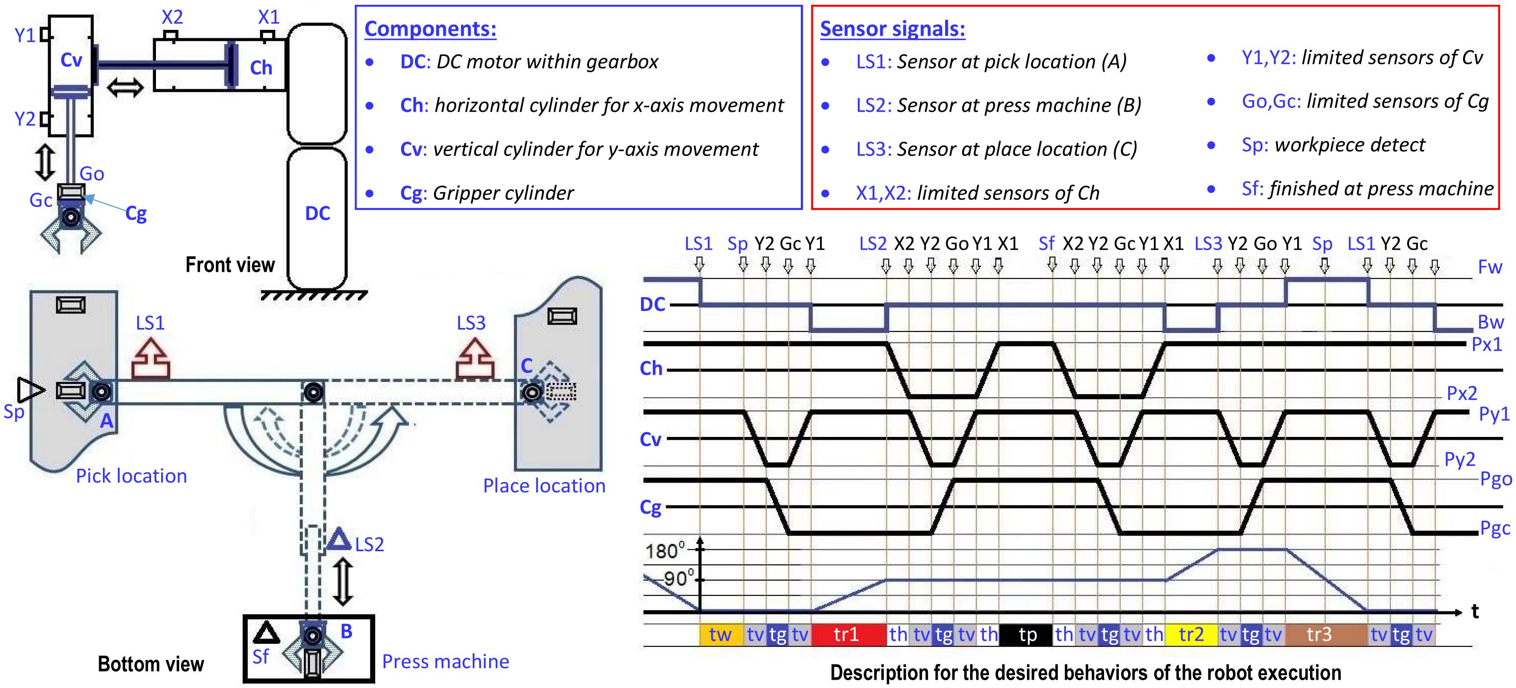
The main goal of this FB is that it can give the requests right and on time for the operation of the PnP system such as: starting/stopping the robot by triggering events StartMotor/StopMotor via the adapter RI, or requesting the rotational movement of the robot by triggering the event CNF (associated with PWM), or requesting the operation of cylinders HorizontalCylinder, VerticalCylinder and Gripper by triggering events ReqCx (associated with DirLinX), ReqCy (associated with DirLinY) and ReqGrip (associated with DirGrip).
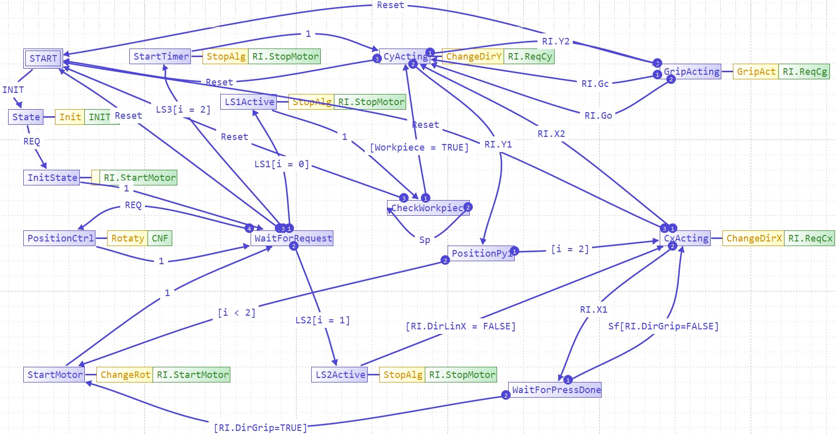
The output data (PWM, DirLinX, DirLinY, DirGrip) and output events (StartMotor, StopMotor, CNF, ReqCx, ReqCy, ReqGrip) are given by the control algorithm as an ECC (Execution Control Chart) of the ControllerFB, it is shown in the figure below.
-
PWM[REAL]: is given by 5 values from the set {-1, -0.5, 0, 0.5, 1}: Its assigned value depends on the combination of the current position of the PnP tobot Position[REAL; Unit: ◦] and the set value of control CtrlPos[REAL; Unit: ◦] and the desired stop position StopPos1[REAL; Unit: ◦] and StopPos2[REAL; Unit: ◦] and the status of events LS1, LS2 and LS3. The rotational movement of the robot from LS1 to LS2 and from LS2 to LS3 will be given by a positive value, while the rotational movement from LS3 to LS2 will be given by a negative value. For instance:
- The PWM value for rotational movement of the robot from LS1 to LS2: If Position < StopPos1 - CtrlPos then PMW = 1 , If StopPos1 - CtrlPos ≤ Position < StopPos1 then PMW = 0.5 and otherwise PMW = 0.
- The PWM value for rotational movement of the robot from LS2 to LS3: If StopPos1 ≤ Position < StopPos2 - CtrlPos then PMW = 1 , If StopPos2 - CtrlPos ≤ Position < StopPos2 then PMW = 0.5 and otherwise PMW = 0.
- The PWM value for rotational movement of the robot from LS3 to LS1: If CtrlPos < Position ≤ StopPos2 then PMW = -1 , If *0 < Position ≤ CtrlPos * then PMW = -0.5 and otherwise PMW = 0
-
Workpiece[BOOL] represents the occurrence of a workpiece. If the Sp-event is triggered and linked with Workpiece = 1 means that a workpiece has occurred.
-
Load[REAL] is used to model the existing of a load during the movement of the robot. When the robot moves from LS1 to LS2 and from LS2 to LS3, the ControllerFB gives to PlantFB a load value specified by LoadIn = Load.The movement of the robot without a load from LS3 to LS1 is represented by the ControllerFB by sending to PlantFB a value is 0 via port LoadIn
-
Te[REAL; Unit: s]: gives the measured duration time from the time point of StartMotor-event occurrence until the StopMotor-event is activated. This value is used in the contract specification of TCFBs.
-
Tc[REAL; Unit: s]: gives the measured duration time from the time point of StartMotor-event occurrence until the controller gives the change for PWM value as described above.
In order to build the model of the production line, we also need to model the other components of the system such as the position sensors, the appearance of a workpiece at the feeding system, and the event for finishing of the processing of the workpiece at the press machine. The other FBs in the model of the system are described as follows:
Sensor[Type: BFB]: is used to detect the appearance of an object at the boundary stop position, which works as limit switch. In this demo, they are named LS1 and LS3, and put at the position 0◦ and 180◦ in the robot working space. This device is featured and operated based on the following parameters:
-
Position[REAL; Unit: ◦]: this data represents the position of the robot relative to the sensor.
-
LimPos[REAL; Unit: ◦]: We can also consider this data as a parameter representing the put position of the sensor.
-
Direct[BOOL]: this data represents the working direction of the sensor. For example:
- If Direct = 1, then the sensor will be triggered whenever the Position ≤ LimPos is detected.
- If Direct = 0, then the sensor will be triggered whenever the Position ≥ LimPos is detected.
-
OUT[BOOL]: represents the active status of the sensor. For example: The Response-event associated with OUT = TRUE will be triggered either at the Position ≥ LimPos and Direct = 0 or at the Position ≤ LimPos and Direct = 1. Otherwise OUT = FALSE
OpticSensor[Type: BFB]: To simulate the system in a realistic way, we create this type of sensor to detect the appearance of an object at the passing locations, for example at the press machine (noted by LS2). This device is featured and operated based on the following parameters:
- Putposition[REAL; Unit: ◦]: represents the position of sensor, where it is placed.
- RateDetect[REAL]: this data can be also considered as the angular spread or the sensing angle of the sensor. For example: the sensor will be trigger when the position of the robot (given at Position ) meets the condition: Putposition(1 - RateDetect) ≤ Position ≤ Putposition(1 + RateDetect).
SupplyConv[Type: CFB]: is used to model the occurrence of a workpiece at the supply conveyor belt of the feeding system. In this FB, we encapsulate a FBN of FBs from the standard library of 4diac including E_DELAY, E_RS, E_PERMIT to get the desire behavior. Its FBN is depicted in the following picture.

-
Whenever a workpiece occurs, it will generate a trigger at WpArrive-event, this event triggers the S-event of the E_RS-FB named Workpiece, therefore it creates a trigger at the EO-event, which is associated with QO = 1 of Workpiece. When the E_PERMIT-FB occurs, a request at EI-event is associated with QI = 1, that leads to the triggering of the EO-event. Thus, at the output side of SupplyConv-FB, a WpExist-event associated with Workpiece = 1 will be also triggered.
-
The WpExist-event can request the next phase of robot execution (it is linked to ControllerFB at port Sp-event) if this event occurs after the LS1 signal has already occurred. In the case where the LS1 signal of the sensor occurs later than this event, theLS1 signal will re-check the existing of the workpiece by triggering a request at EI-event of E_PERMIT.
-
In this work, we assume that the robot allows a waiting time for a workpiece of maximal 1s. This means, for a regular operation, the system must ensure that whenever LS1-signal occurs then after than 2s the workpiece has to not exist anymore at the supply conveyor belt of the feeding system (it has already transferred by the robot before). Therefore, we use an E_DELAY-FB with a fixed value of T#2s to model this requirement.
In addition, to model the execution at the press machine, we assume that, whenever the LS2-signal occurs, after 4s, the Sf-event will occur. For this, we use the E_DELAY-FB of the 4diac standard library.
In our work, we aim to develop a control system for a pick & place robot (PnP) in a production line, its desired behaviors is shown in following video.
We develop the system to model the real behavior and properties of the manufacturing process by arranging and connecting these FBs together through their respective interface events and data. The system model without the application of contracts is built as an IEC 61499 application named SystemWithoutContracts. It is shown in the following picture:
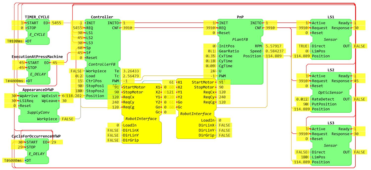 In this demo, we assume that the subsystems operate interdependently within a given time cycle. When a subsystem does not meet its timing requirements it will lead to error in the overall system. With this model, we can recognize that the operating accuracy of the controller completely depends on the accuracy of the sensors. Now, we can give the following scenarios for the system.
- Scenario 1: The position of the sensors is wrong, for example: if the LS1-sensor is put at the wrong position and its position is either greater (see this video) or less (see this video) than the allowed error, the controller will also stop the robot at the wrong position. This leads to the effect that the robot cannot take the workpiece for the next execution cycle of the system.
- Scenario 2: Waiting for the occurrence of a sensor event, such as LS1, LS2, LS3, Sp, Sf. In this case, if either the sensor is broken or the workpiece feeding system (see this video) or the press machine(see this video) does not work , then the controller must give a decision for this situation, instead of continuing to wait for the signal from that sensor.
- Scenario 3: The execution time of a subsystem is slower/faster than the timing requirement of the overall system. This affects the operating sequence of the next component or next process in the system.
We realize that our simple controller is currently unable to handle these scenarios. For this reason we are now introducing timing contracts into the model, which are able to detect the occurrence of these scenarios and deal with them appropriately (the error handling itself is not in the scope of this demo).
TCFB[Type: BFB]: to address the mentioned issues above, we create a FB for specifying timing aspects. The so-called Timing Contract Function Block (TCFB). This FB observes the time aspect of events and that they comply with the defined time constraints. The operating principle of this FB including the properties and features of event and data ports has already been described in our paper.
Note that the TCFB is controlled by the input data port QI. If the ReqEvent linked with QI = TRUE is present, the TCFB is activated. Otherwise this FB will not be activated and QO = FALSE.
EnableCheck[Type: BFB]: In this demo, the system is operated comply within an execution cycle. That leads to a situation in which we need to permit the execution of the first component/process in the first cycle.In the next cycle, this component/process must be operated/triggered by the satisfaction of the timing contract of the last component/process in system. To address this cyclic chain initialization issue, we created an EnableCheck FB to check the permission for beginning a new execution cycle of the system. In particular, this FB checks whether the last execution cycle of the behavioral FBs satisfied its guarantees and activates the next execution cycle. The operating principle of this FB, including the properties and features of event and data ports is described as follows:
- The REQ-event is associated with the input data QIi([BOOL]) and QIt([BOOL]). The input data QIi([BOOL]) represents the permission in the first request of this FB:
- If QIi = 1 or TRUE then this FB is permitted in the first request
- If QIi = 0 or FALSE then this FB is not permitted in the first request
- The REQ occurs for the first time:
- If the REQ-event associated QIi = 1 or QIi =TRUE is triggered, then the Satisfied-event associated with the input data QO([BOOL]) = TRUE will be activated
- If the REQ-event associated QIi = 0 or QIi =FALSE is triggered, then the Violated-event associated with the input data QO = TRUE will be activated
- The REQ occurs for the next times:
- If the REQ-event associated QIt = 1 or QIt =TRUE is triggered, then the Satisfied-event associated with the input data QO = TRUE will be activated.
- If the REQ-event associated QIt = 0 or QIt =FALSE is triggered, then the Violated-event associated with the input data QO = TRUE will be activated
SplitInitEv[Type: BFB]: because of the difference between the first and the following iterations of the execution cycle of component/process in the system (as mentioned above), we create this FB for splitting the first event from all following events of a request event. The operating principle of this FB is described as follows:
- When the REQ-event occurs for the first time, then the CNF-event and FirstTime-event will be activated.
- When the REQ-event occurs not for the first time, then the CNF-event and NextTime-event will be activated.
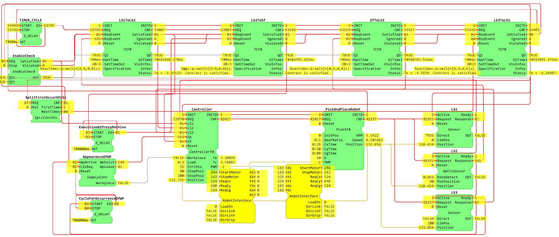
In our approach for contract-based controller design, we want to ensure the timing constraints of all components and the overall system. Instead of directly connecting the sensor signals with the request events of the controller as shown in above picture, we will observe and measure them first by timing contracts before they can trigger the execution of control algorithms. The system model with application of timing contracts is built as an IEC 61499 application named SystemApplyTimingContracts. It is used for monitoring the system and depicted in the figure below:
We use the TCFBs named LS1ToLS2, LS2ToSf, LS3ToLS1, and SfToLS3 to specify the timing constraints for the execution time for the robot (this execution time is measured by a span time between the occurrence of the sensor signals (LS1, LS2, LS3)), and the execution time at the press machine. These FBs use all the same principle for the connection of events and the same setup values, such as:
- The REQ-event of the previous TCFB is connected to the CNF-event of the next TCFB. In addition, the CNF-event of the last TCFB will be linked to the E_DELAY-FB with set value of 20ms to generate the cycle time for the REQ-event of the first TCFB. This cycle is also used to check the timeout of the TCFB.
- The Satisfied- and Violated-events of the previous TCFB are connected to the ReqEvent of next TCFB. Besides that, the outdata QO of the previous TCFB is linked to the input data QI of the next TCFB. The reason for this connection principle is given as follows:
- If the previous TCFB meets the timing requirements, it will active the Satisfied-event, associated with QO = 1. That leads to the next TCFB, which is activated by its ReqEvent associated with QI = 1.
- If the previous TCFB does not meet the timing requirements, it will active the Violated-event, associated with QO = 0. That leads to the deactivation of the next TCFB by its ReqEvent associated with QI = 0. In this case, the deactivation for next FBs comply with a sequence reaction.
- The Satisfied- and Violated-events of the last TCFB are connected to the REQ of the EnableCheck-FB. Besides that, the outdata QO of the last TCFB is linked to the input data QIt of the EnableCheck. The Satisfied- and Violated-events of the EnableCheck-FB are connected to the ReqEvent of the first TCFB. The outdata QO of the EnableCheck is linked to the input data QI of the first TCFB. The reason for this connection principle will be explained in the following part.
- GetTime([TIME]): is set to 0. This value represents the time variable of the FB, which is calculated based on its local time (it depends only on the time point of occurrences of ReqEvent and RspEvent).
- SetTimeOut([REAL; Unit: s]): is set to 20.3. The reason for selecting this value has already been explained in our paper.
The difference of data setting of these FBs are shown as follows:
LS1ToLS2-FB: we use this FB to constrain the robot execution time in the time interval by the timing contract: "Whenever signal LS1 occurs then signal LS2 occurs within the interval [3.5,3.8]s". It is described by the following syntax:
Reaction::q->e(i|=[3.5,4.8]s)
- The above syntax is defined at the data port Specification([STRING])
- In this demo, the SplitInitEv-FB (named SplitFirstOccurOfLS1) is use to split the LS1 signal from the sensor named LS1. Its connections is described as follows:
- In the first time of the execution cycle, the signal from LS1 will be not constrained by any signals. It can be considered as a satisfaction contract in the first request. The FirstTime-event is linked to the first time occurrence of the LS1 signal. This signal will request the REQ-event associated with QIi = 1 of EnableCheck-FB for the first time. That leads to the request of LS1ToLS2 by EnableCheck.Satisfied at ReqEvent associated with QI = 1 for the first time.
- In the next times of the execution cycle, the signal from LS1 is linked to the RspEvent of LS3ToLS1 via the event port NextTimes of the SplitInitEv-FB. This case will be described in the explanation of LS3ToLS1.
- The EnableCheck-FB will trigger the LS1-event of the Controller-FB if the Satisfied-event is activated, otherwise the event Controller.LS1 will not be required.
- The RspEvent is connected to the sensor FB LS2.Response. This can lead to two case of decision of LS1ToLS2-FB:
- If the occurrence of the LS2 signal meets the requirement of the timing constraint of the LS1ToLS2-FB, it will active the Satisfied-event associated with QO = 1 to request the execution of the LS2ToSf-FB. At the same time, it triggers the LS2-event of the Controller-FB.
- If the occurrence of the LS2 signal does not meet the requirement of the timing constraint of the LS1ToLS2-FB, the Violated-event associated with QO = 0 will be triggered to deactivate the LS2ToSf-FB (due to the LS1ToLS2.Violated is connected to the port LS2ToSf.ReqEvent). In parallel with that, the LS2-event of Controller-FB will not be required.
LS2ToSf-FB: We use this FB to constrain the execution time at the press machine by the following timing contract: "Whenever signal Sf occurs then signal LS2 has occurred within the interval [3.9,4.4]s ". It is described by following syntax:
Age::q->e(i|=[3.9,4.4]s)
- The data port Specification is set as "Age::q->e(i|=[3.9,4.4]s)"
- The RspEvent is connected to the EO-event of E_DELAY-FB named ExecutionAtPressMachine to check the occurrence of the sensor signal Sf.This can lead to two case of decision of LS2ToSf-FB:
- If the occurrence of the Sf signal meets the requirement of the timing constraint of the LS2ToSf-FB, it will active the Satisfied-event associated with QO = 1 to request the execution of SfToLS3-FBs. At the same time, it will trigger the Sf-event of the Controller-FB.
- If the occurrence of Sf signal does not meet the requirement of the timing constraint of the LS2ToSf-FB, the Violated-event associated with QO = 0 will be triggered to deactivate the SfToLS3-FB. In parallel with that, the Sf-event of the Controller-FB will not be required.
SfToLS3-FB: We use this FB to constrain the execution time at the press machine by the following timing contract: "Whenever Sf signal occurs then LS3 signal will be occurred within the interval [4.1,4.6]s ". It is described by following syntax:
Reaction::q->e(i|=[4.1,4.6]s)
- The data port Specification is set as "Reaction::q->e(i|=[4.1,4.6]s)"
- The RspEvent is connected to the sensor FB LS3.Response. This can lead to two case of decision of SfToLS3-FB:
- If the occurrence of the LS3 signal meets the requirement of the timing constraint of the SfToLS3-FB, it will active the Satisfied-event associated with QO = 1 to request the execution of the LS3ToLS1-FB. At the same time, it triggers the LS3-event of the Controller-FB.
- If the occurrence of the LS3 signal does not meet the requirement of the timing constraint of the SfToLS3-FB, the Violated-event associated with QO = 0 will be triggered to deactivate the SfToLS3-FB. In parallel with that, the LS3-event of the Controller-FB will not be required.
LS3ToLS1-FB: We use this FB to constrain the execution time at the press machine by the following timing contract: "Whenever LS3 signal occurs then LS1 will be occurred within the interval [6.2,6.5]s ". It is described by following syntax:
Reaction::q->e(i|=[6.2,6.5]s)
- The data port Specification is set as "Reaction::q->e(i|=[6.2,6.5]s)"
- The RspEvent is connected to the NextTimes of the SplitInitEv-FB. This can lead to two case of decision of the LS3ToLS1-FB:
- If the occurrence of the LS1 signal meets the requirement of the timing constraint of the LS3ToLS1-FB, it will active the Satisfied-event associated with QO = 1 of LS3ToLS1 to request the next execution cycle of the system, specifically it will trigger the REQ-event associated with QIt = 1(this port is connected to LS3ToLS1.QO = 1) of the EnableCheck-FB for request the ReqEvent associated with QI = 1 of LS1ToLS2.
- If the occurrence of the LS1 signal does not meet the requirement of the timing constraint of the LS3ToLS1-FB, the Violated-event associated with QO = 0 of LS3ToLS1 will be triggered to stop the next execution cycle of system, specifically it will trigger the REQ-event associated with QIt = 0 of the EnableCheck-FB to deactivate the LS1ToLS2-FB through a request ReqEvent, associated with QI = 0.
In order to test this demo, you will need to download and install 4diac-IDE. The installation of 4diac IDE is independent of the operating system. Note that the 4diac IDE requires at least Java 8.
As mentioned above, in this demo, we created applications named SystemWithoutContract, ApplyTimingContracts, and TestSystem. These applications are mapped to two resources of the device FORTE_PC named CPU1, CPU2, and Test respectively. To deploy an application in 4diac, you need to perform following steps:
- Step 1: You need to build suitable FORTE for deploying an application. The detail guides for building 4diac FORTE can be found in this webpage. Please remember that we used the 4diac FOTRE Version 1.11.3 to build the runtime environment for this demo.
- Step 2: In 4diac, go to Windows → Preferences → 4diac IDE → FORTE Preferences to set FORTE as selection for deploying applications, and then click Apply and Close.
- Step 3: Change to the Deployment Perspective.
- Step 4: Set the port to 61499 in Local FORTE and Click Launch Local FORTE.
- Step 5: Select the elements to deploy. For this demo you can select resource CPU1 or CPU2 or Test of the FORTE_PC and deploy the SystemWithoutContract or ApplyTimingContracts or TestSystem then Click the Deploy button.
- Step 6: Change to the System Explorer, right click on the name of System → Monitor System
- Step 7: In the Application Editor, open the selected application, choose all FBs in this application and Right Click on a FB → Watch All to observe the status of input and output events, as well as input and output variables of FBs.
This way, you can deploy and monitor an application in 4diac.
The instructions for running and testing the system without timing contracts is presented in this video.
In order to test the capability of ensuring the safe operating of the system model by using the timing contracts, in the cases of occurrence of the unexpected scenarios as mentioned above, we added some FBs of E_SWITCH-Type named OnOffLS1, OnOffLS2, OnOffLS3, OnOffFeedingSystem and OnOffPressMachine into the SystemApplyTimingContracts to model the loss of the sensor signals LS1, LS2, and LS3, as well as the feeding system, and the press machine. The system model is shown in the following picture:
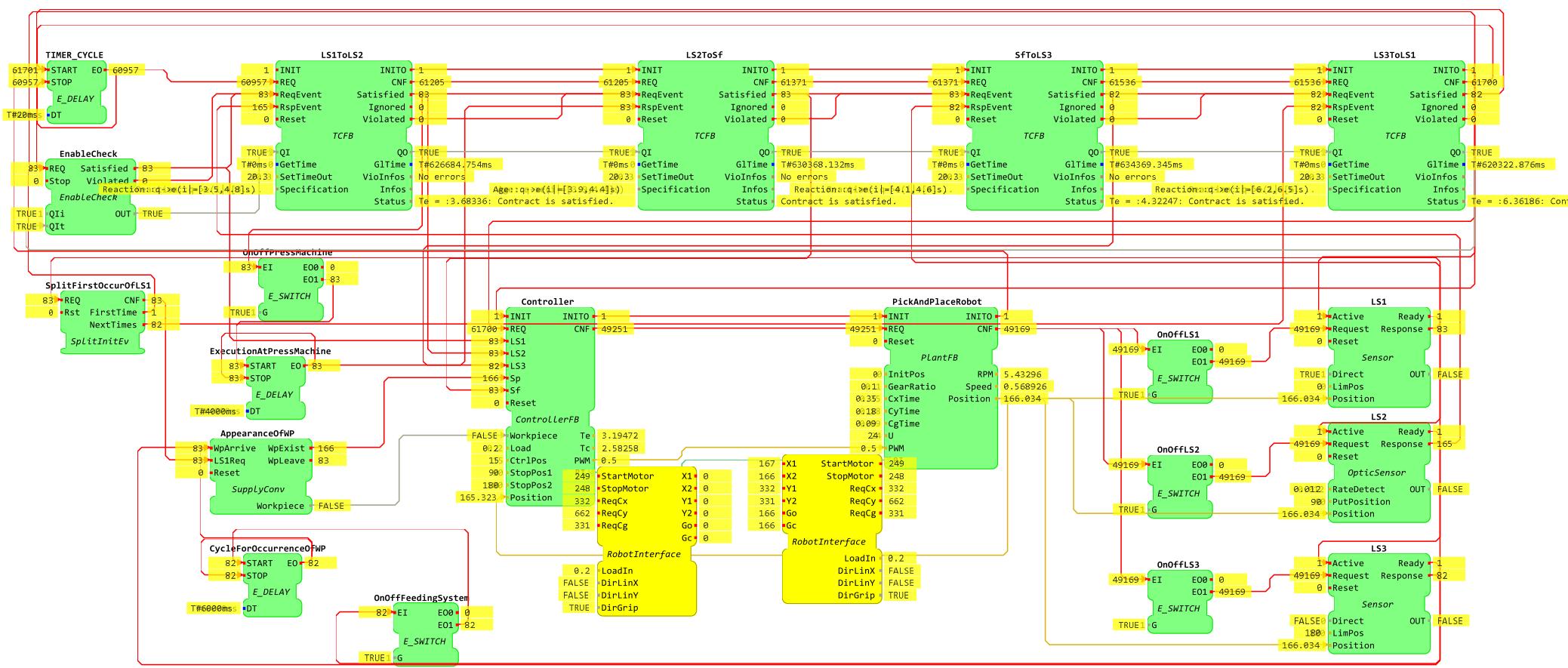
The testing process is performed in the following videos: Video 1 and video 2
Copyright (c) 2020 OFFIS e.V.
This program and the accompanying materials are made available under the terms of the Eclipse Public License 2.0 which is available at http://www.eclipse.org/legal/epl-2.0
SPDX-License-Identifier: EPL-2.0
