HiSpeed
At times we want to respond immediately to asynchronous signals on our microcontroller's pins. Perhaps we can't wait for a running program to attend to a periodic signal and we want to make sure that when we receive an event it is acknowledged or flagged without delay. Or we may not want to pollute our main code with polling routines that query the pins which would introduce design challenges or bugs. Thus all or nearly all computer chips today have an interrupt system built into them. Interrupts allow the main routine to be stopped at any point and a specialized routine called an Interrupt SubRoutine (ISR) is run.
Ideally there will be no latency between the signal and the ISR reponse. However, in real electronic circuits there is always some latency- at the very least in gate propogation delay (the amount of time it takes for a signal to get from input to output of a gate). But in microprocessors latency may be significantly longer than simple propagation delay, mostly having to do with the synchronization of its internal circuitry.
In the case of the ATmega processors used in the Arduino we have additional issues. When an interrupt occurs, the interrupt subroutine (ISR) must save the contents of all the CPU registers that it is going to- or may- use. Additionally the compiler inserts other boilerplate code that takes yet more time. On higher-end (that is, larger, faster, and more expensive) processors this is handled in the hardware but in the ATmega Arduinos the software handles the housekeeping. By software I mean the software used in your sketch, whether you program your own ISR or use a library. It may not be obvious but it's compiled in there and it takes time.
Although valuable and necessary, this saving action is overhead. It is best to minimize it- to keep it as short as possible. This is difficult in a general-purpose library which calls subfunctions that are not known ahead of time. However, by limiting the functions in an ISR we can allow the compiler to optimize the overhead and thus reduce ISR time.
We endeavor to speed up ISRs by instead of calling subfunctions from within them, simply incrementing a variable of the programmer's choice which can be queried later. This limits the number of registers needed to be saved and restored and speeds up the ISR.
The EnableInterrupt library has a mode whereby the ISRs do not call a user-defined subroutine but instead increment a chosen variable. This is called "HiSpeed mode". Tests show that this greatly increases the speed of the ISRs. Here are typical results:
For the EnableInterrupt library, on a single Pin Change interrupt pin calling a single function that increments a volatile variable (ie, one stored in static RAM) on the ATmega328p processor, it took (note that that is the default (non-HiSpeed) mode of the library):
- 8.4 microseconds
- 4.8 microseconds
- 2.4 microseconds
- 12.9 microseconds
A sketch called "HiSpeedTest.ino" was used to measure interrupt timing. This script was run on an Arduino Duemilanove platform. It defines pin 8 as the interrupt pin for Pin Change Interrupt tests. Pin 2 was used for the External Interrupt test. There are a number of macros that were used to control the sketch:
- The
OLDLIBRARYmacro if defined includes the PinChangeInt library rather than the EnableInterrupt library. - One of the
THEINTERRUPTPIN8orTHEINTERRUPTPIN2macros were defined to control which pin was the pin under test. All pins on the ATmega328p are available as Pin Change interrupt pins; pin 2 is also defineable as an External Interrupt pin and the EnableInterrupt library will utilize External interrupts by default on any pin which supports them. Note that External interrupts are not supported by the PinChangeInt library so definingTHEINTERRUPTPIN2is not possible when using that library.
loop() the pin is changed to HIGH level by setting the proper pin on the proper
PORT. That C code compiles to an sbi assembly language instruction which takes
1 clock cycle to run. Therefore the timing results are within +62.5/-0 nanoseconds, which is a small
fraction of the ISR's timing.
After the interrupt returns, within loop() the pin is changed to LOW level by
setting the proper pin on the chosen PORT. That C code compiles to a cbi assembly
language instruction which takes 1 clock cycle to run. Therefore the timing results are again
within +62.5/-0 nanoseconds.
See the tests, below, for code samples which demonstrate these algorithms.
Initially, the code in loop() which triggered the interrupt looked like this:
PININTERRUPT_ON;
PININTERRUPT_OFF;
which are defined as:
PORTB |= (1 << PB0);
PORTB &= ~(1 << PB0);
respectively. These translate to assembly language instructions SBI and CBI, which take only 1 clock cycle to execute and produced a very short pulse (~62 ns) on the pin under test, pin 8.
But perusing of the assembly language output of the ISR showed that it should take some number of microseconds to enter and exit, and other code later in the loop printed the value of the interrupt counter variable and it remained at 0. Obviously the loop was performing but the interrupt was not getting called.
Therefore, I inserted a sufficent number of assembly language NOP instructions, here represented in C by
_NOP(); (see avr/cpufunc.h), until suddenly the pulse width of
the signal generated by PININTERRUPT_ON and PININTERRUPT_OFF jumped from a small multiple of
62.5 ns to a couple of microseconds. At the same time, the interrupt counter variable climbed.
NOP takes 1 clock cycle to execute and gives the processor time to recognize the interrupt; see Figure 12-1 on
p. 70 of the ATmega48A/PA/88A/PA/168A/PA/328/P Datasheet, document Atmel-8271I-AVR- ATmega-Datasheet_10/2014.
After 3 NOP's were inserted the code looked like this:
  PININTERRUPT_ON;
  _NOP();
  _NOP();
  _NOP();
  PININTERRUPT_OFF;
and the pulse looked like this:

Notice that the pulse is about 300 ns long; as the 3 NOPs are 186 ns themselves this is far too short to include an interrupt. Finally, a fourth NOP was added and suddenly the signal went from a few hundred nanoseconds to microseconds in length, as we will see in the next test. Thus we have found the approximate minimal duration of a signal on a Pin Change interrupt pin- 4 * 62.5 nanoseconds.
See Test 2 for a picture of the signal pulse including interrupt, and further discussion.
As discussed above, this test involved:
- Activating an ISR by bringing port 8 high,
- Running 4 NOP instructions,
- Bringing port 8 low.
The sketch's loop code looked like this:
  PININTERRUPT_ON;
  _NOP();
  _NOP();
  _NOP();
  _NOP();
  PININTERRUPT_OFF;
The ISR code looked like this:
#define INTERRUPT_FLAG_PIN8 myvariable_pin8
...
ISR(PORTB_VECT) {
  uint8_t current;
  uint8_t interruptMask;
  uint8_t changedPins;
  uint8_t tmp;

  current=PINB;
  changedPins   = portSnapshotB ^ current;
  tmp           = risingPinsPORTB & current;
  interruptMask = fallingPinsPORTB & ~current;
  interruptMask = interruptMask | tmp;
  interruptMask = changedPins & interruptMask;
  interruptMask = PCMSK0 & interruptMask;

  portSnapshotB = current;

  if (interruptMask & _BV(0)) INTERRUPT_FLAG_PIN8++;
}
The signal pulse looked like this:

This is a closeup of the end of the signal:

Here we can see that the duration of the ISR, including preamble, postamble, and necessary delay to recognize the interrupt(ie, _NOP() statements), was 4.78 microseconds (see the orange "T" in the lower right-hand corner)..
To compare the benefits of the HiSpeed mode, we run the sketch without #define'ing NEEDFORSPEED. Thus, the ISR will run the following code:
void incrementMyVariable() {
  THEINTERRUPTVARIABLE++;
}
where THEINTERRUPTVARIABLE is defined in a macro as myvariable_pin8,
a variable of type uint8_t. The actual ISR that runs is:
ISR(PORTB_VECT) {
  uint8_t current;
  uint8_t interruptMask;
  uint8_t changedPins;
  uint8_t tmp;

  current=PINB;
  changedPins   = portSnapshotB ^ current;
  tmp           = risingPinsPORTB & current;
  interruptMask = fallingPinsPORTB & ~current;
  interruptMask = interruptMask | tmp;
  interruptMask = changedPins & interruptMask;
  interruptMask = PCMSK0 & interruptMask;

  portSnapshotB = current;

  if (interruptMask == 0) goto exitPORTBISR; // get out quickly if not interested.
  if (interruptMask & _BV(0)) portBFunctions.pinZero();
  if (interruptMask & _BV(1)) portBFunctions.pinOne();
  if (interruptMask & _BV(2)) portBFunctions.pinTwo();
  if (interruptMask & _BV(3)) portBFunctions.pinThree();
  if (interruptMask & _BV(4)) portBFunctions.pinFour();
  if (interruptMask & _BV(5)) portBFunctions.pinFive();
  if (interruptMask & _BV(6)) portBFunctions.pinSix();
  if (interruptMask & _BV(7)) portBFunctions.pinSeven();
  exitPORTBISR: return;
}
Arduino pin 8 on the ATmega328 is PB0, so portBFunctions.pinZero() was assigned to incrementMyVariable() and it will be the function that runs, although all the other if statements are subsequently checked as well.
The results are shown here:
 .
.
Here we zoom into the trailing part of the pulse, with the transition to low measured at time T: 8.56 microseconds:
 .
.
Thus the additional code to call the user's function, plus the additional if statements, added almost 4 microseconds to the total ISR time.
By comparison, I would like to compare the EnableInterrupt library to the old PinChangeInt library found at https://github.com/GreyGnome/PinChangeInt . The same function call is used as in Test 3. The PinChangeInt code was written using C++ and its ISR depends on C++ PORT objects and a linked list of pin objects; I would expect it to be significantly slower.
Here is what the ISR looks like, edited for brevity. The PCintPort::PCint code is a method defined for each PORT object (represented by the PCintPort class in code).
void PCintPort::PCint() {

        uint8_t pcifr;
        while (true) {

            PCintPin* p = firstPin;
            uint8_t changedPins = (PCintPort::curr ^ lastPinView) &
                                  ((portRisingPins & PCintPort::curr ) | ( portFallingPins & ~PCintPort::curr ));
            while (p) {
                // Trigger interrupt if the bit is high and it's set to trigger on mode RISING or CHANGE
                // Trigger interrupt if the bit is low and it's set to trigger on mode FALLING or CHANGE
                if (p->mask & changedPins) {
                    PCintPort::arduinoPin=p->arduinoPin;
                    p->PCintFunc();
                }
                p=p->next;
            }
            pcifr = PCIFR & PCICRbit;
            if (pcifr == 0) break;
            PCIFR |= PCICRbit;
            PCintPort::curr=portInputReg;
       }
}
The result is shown here: 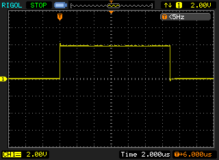
We zoom into the trailing edge here:
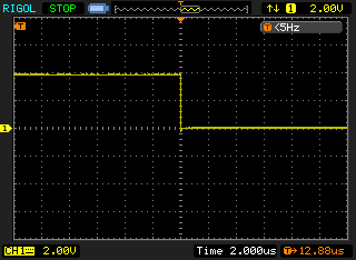
with the transition to low measured at time T, the value is: 12.88 microseconds. Thus this added over 4 microseconds to the total ISR time, above the EnableInterrupt library's normal mode ISR. The EnableInterrupt library demonstrates a significant speedup.
External interrupts in the Arduino are called "normal" or "high speed" interrupts. This is because the interrupt system is set to trigger on the desired transition/level in hardware: either RISING, FALLING, or CHANGE, or LOW value. By the time your ISR is called, you already know which pin triggered the interrupt and you know what the transition type was. The tradeoff is that the number of External interrupts is limited.
By default the library will utilize an External interrupt on any pin that supports them. Across the ATmega CPU landscape used on the Arduino, there is one chip type- the ATmega168/328- that shares interrupt types on Arduino Uno pins 2 and 3. For these, the programmer can choose the interrupt type to use by ORing the pin number with the PINCHANGEINTERRUPT macro (0x80 in Hex) to pick Pin Change interrupts. Otherwise, External interrupts will be preferred. These are the only pins on which this choice applies. This choice is not necessary or available on the Leonardo or Yun, or on the ATmega2560-based Arduinos like the Mega2560.
In any event, let's see how much faster External interrupts are over Pin Change interrupts. The ISR code is much different:
#define INTERRUPT_FLAG_PIN2 myvariable_pin2
...

ISR(INT0_vect) {
  INTERRUPT_FLAG_PIN2++;
}
Notice there is no code necessary to select the Pin number or the mode. Each External interrupt ISR applies to only a single pin, and the mode is chosen ahead of time so the programmer is aware of what sort of transition triggered the ISR. This should be significantly faster, and indeed the results show this:

Also note that in this snapshot the grid is 500ns long in the x-direction, so the total length if the ISR is less than 2.5 microseconds. This is an excellent speed increase and a big win over the original PinChangeInt code; even over the EnableInterrupt library in normal mode. If you need to track signals that are in the hundreds of kilohertz range this would be the mode to use. But the signal should still be significantly under 400 khz (1 / 2.5 microseconds) so as to not starve the main loop.
The EnableInterrupt library is a significant advancement over the (relatively) popular PinChangeInt library in both speed and ease of use. It encompasses not only Pin Change interrupts but External interrupts, and it can be used on the Arduino Due as well, thus providing a consistent API over all interrupt types on all Arduino platforms. The HiSpeed mode presents a great speed improvement over the normal library functionality if the programmer is willing to accept the tradeoffs presented by using this technique.