Here are instructions for making a LED strip that can be controlled via an Web API.
The strip can show any color combination with red, green and blue LEDs:

LEDs can be controlled individually. Here is a flame effect:
The LED API can receive a number of commands. Number parameters are given as two-digit hex numbers. Colors are given as three two-digit hex numbers, for red, green and blue color component.
Commands are sent as query parameters of a HTTP GET request to the
server. For example http://<hostname>/?s808000.
| Command | Description | Format | Example | Explanation |
|---|---|---|---|---|
| c | clear all pixels | c | c | turns off all pixels |
| s | set all pixels to a single color | s[color] | sff00ff | set all pixels to bright magenta |
| p | draw a single pixel | p[position][color] | p28ffffff | set pixel number 40 (0x28 in hex) to white |
| a | set colors from an array | a[number of pixels][color1][color2]... | a03ff0000ffff0000ff00 | set three colors: red, yellow and green |
| g | draw a color gradient | g[start position][end position][color1][color2] | g0010ff0000ffff00 | draw a 16 pixel gradient from red to yellow at the start of the led strip |
| m | draw a moving sprite | m[background r][background g][background b][size of sprite][sprite position][sprite speed][color1][color2]... | m000000040084000500003000006000ffffff | animate a white pixel with green fading tail quite slowly slowly on a black background |
| f | animate flames | f[fuel amount][damping amount] | f2f10 | |
| b | animate aurora borealis | b[speed][centering][center color][edge color] | b240150ff5005ff05 |
When the microcontroller starts, it initializes the WiFi shield and the LED strips, then connects a WiFi router and sets up a HTTP server listening on port 80.
Add name and password of your WiFi router in server/credentials.h.
The main loop does the following: When a HTTP client is available, it reads a line from the request, processes the command and send a response to the HTTP client. Finally the loop updates the LEDs.
Here is a simplified version of the main loop in `server/server.ino:
void loop() {
  WiFiClient client = server.available();
  if (client) {
    currentLine = readLine(client);
    client.flush();
    processLedCommand(currentLine);
    client.println(httpResponse);
    client.stop();
  }
  updateLeds();
}- LEDs: 4 meter Adafruit DotStar Digital LED Strip that has 240 individually-addressable RGB LEDs
- microcontroller: Adafruit Feather M0 WiFi - ATSAMD21 + ATWINC1500 Arduino board with WiFi capability.
- power supply: 5V 10A switching power supply for the LEDs
Here is a schematic of how the power supply (on the left), microcontroller and LED strip (on the right) are connected:
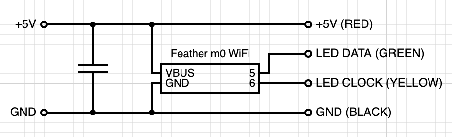
| Pin | Description | Wire color |
|---|---|---|
| GND | ground | black |
| VBUS | 5V power | red |
| 5 | data to led strip | green |
| 6 | clock to led strip | yellow |
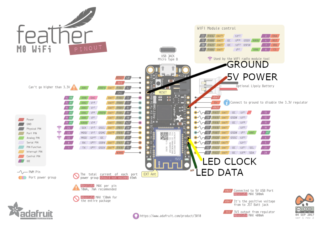
Feather M0 pinouts without annotations
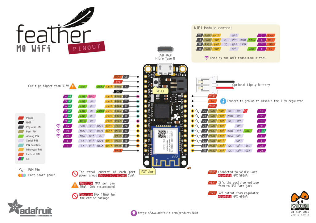
Here is everything put together in the enclosure:
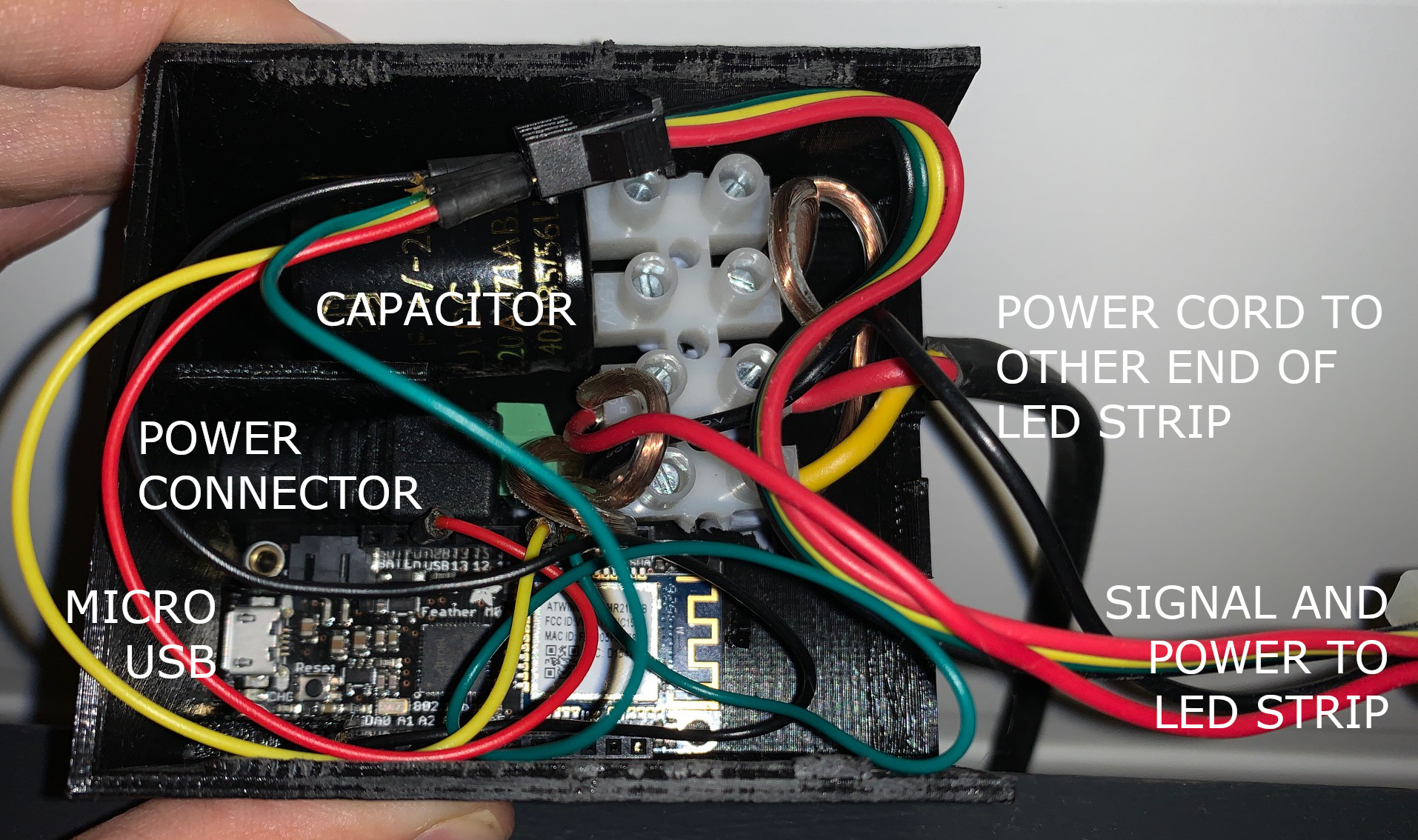
Image of finished enclosure without annotations
There is a Micro USB connector for flashing the microcontroller. I added a power cord that goes to the other end of the LED strip to make sure that all leds receive power evenly.
The enclosure is 3D printed and has a sliding lid.
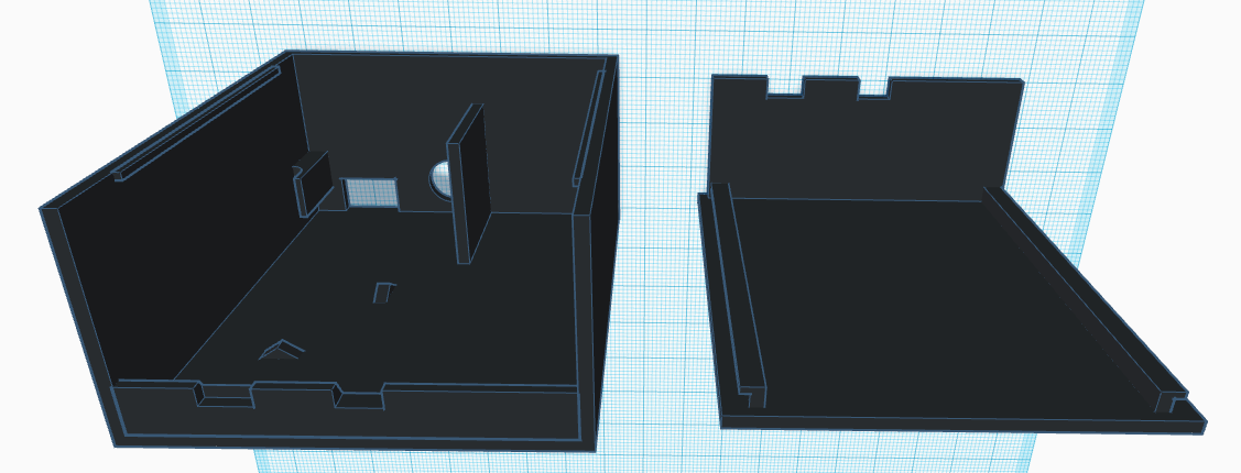
Here are the 3D models of the bottom and lid of the enclosure: