DO NOT USE THIS WITH THE MONOPRICE MINI DELTA V2! THIS TUTORIAL IS FOR THE OLDER MONOPRICE MINI DELTA V1!
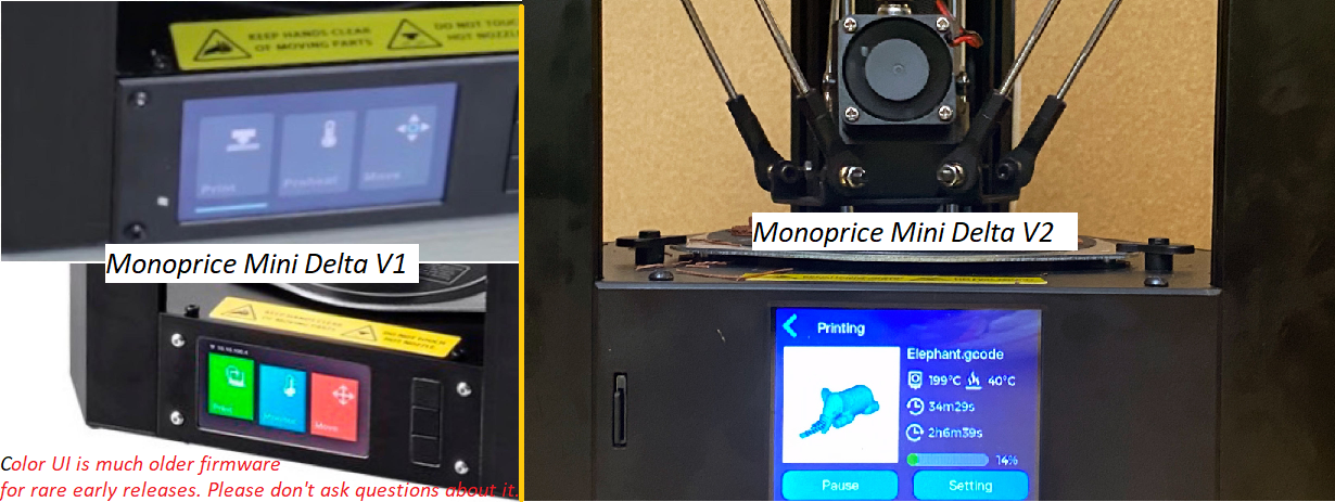
The firmware for these two machines behave very differently. The Monoprice Mini Delta V2 already includes a built-in Delta Calibrate routine, so do not use these scripts/programs.
THIS TUTORIAL IS ONLY FOR auto_cal_generic.py...NOTHING ELSE!!!
If you're trying to tackle advanced calibration, then it is assumed that you have already gone through the steps outlined in the Calibration Roadmap. If not, then do not act surprised when things do not work well for you. I will add some extra reminders here, but this page is not comprehensive. Also, this page isn't for the basic "I don't know how to connect to USB, why bed not level, what is EEPROM, what is start gcode?" types of questions. Go back to MPMD 101 and (later on) the P5 script tutorial if you need that level of help.
Not all calibration tutorials are correct, and not all correct calibration tutorials are compatible with one another. That being said, the following links may provide helpful background information if you find yourself wanting to know more, beyond what is covered on this page:
Calibration Roadmap
Dennis's Original Facebook Tutorial
Marlin4MPMD Calibration Wiki
RepRap Delta Kinematics Page
If you only care about bed leveling (not dimensional accuracy), then this script might be overkill for you. The tried-and-true stock firmware P5 tutorial or the routines built into the MPMD Marlin 1.1.X Quick-Start Guide might suit your needs with much less fuss.
This is a Python script and I have no plans on converting it to an executable or batch file. If you want to perform this level of calibration, then you can figure out how to run it via Python. There are plenty of instructions on how to make this work in the P5 tutorial page, including a screenshot for WinPython (just use this script instead of the auto_cal_p5_v0.py script). If you do not explicitly define an input value, then the script will choose a default value.
In order to maintain consistency with long-standing guides in Dennis's Original Facebook Tutorial, the Calibration Roadmap, and the MPMD Basic Dimensional Accuracy Improvement Video, the rest of this tutorial will assume that you took this approach of adjusting M665 R to improve dimensional accuracy. When it comes to adjusting other M665/M666 parameters, this is intended for use with Dennis Brown's ratio equation (covered later), which is included in all of my Python scripts and Dennis's P5 Heat Map Spreadsheet.
However, if you just want to make adjustments using G33 (without the Python script), or some other calibration method outside of this tutorial, then you will likely have to adjust M665 L manually for dimensional accuracy. I.E., most other delta calibration tutorials that I have found use a straightforward process for adjusting M665 R, but leave it up to the user to adjust M665 L for dimensional accuracy.
Much like the P5 tutorial, I WILL NOT HELP YOU AT ALL UNLESS YOU FILL OUT THE TROUBLESHOOTING FORM. As a matter of fact, you are on the advanced tutorial page now, so things get a little hairier, anyways. Things are not quite as cut-and-dry here, so you may have to do your own experimentation.
-
Generic disclaimer/remark about this being a highly experimental sandbox type of script. There has been very little testing and results may vary. I am not responsible if you brick your printer or otherwise render it unusable. The code is open source. You can see for yourself exactly what it is doing and it is fully your responsibility if you choose to use it.
-
If for some reason you've made it this far and you're relying on the stock built-in stock firmware WiFi (not Octopi), then you might have trouble running the carbon paper test from the script prompt. Just print the gcode file, instead.
-
Sometimes aegean-odyssey's MPMD Marlin 1.1.X returns a firmware error when running G33 ("Correct delta settings with M665 and M666"). This is not something that I have control over via the script. Either use a different calibration pattern option or find an M665 combination that does not cause this error to appear. It might be as easy as changing M665 V (M665 B calibration radius in regular Marlin).
Don't act surprised if you get terrible calibration results on a stock machine. Here are some recommended hardware alignments/calibrations/upgrades.
-
General cleaning, lubrication, belt tuning, part inspection, making sure no nuts are loose, recalibrating the bed clips, etc.
-
You absolutely must do something to address/calibrate the precision/consistency/activation of the bed leveling switches. I.E., you need to ensure that the bed switches activate at the same distance every time the bed is probed, regardless of where the bed is probed. You also need to know what that probe distance is. I highly recommend using well-tested bed hold-down clips.
-
The bed surface needs to be completely consistent so that the nozzle probes the exact same surface height for every point. Yes, a height difference the thickness of tape or a sticker makes a huge difference.
-
The bed should preferably be a perfectly flat glass plate or a mirror. I recommend either a thermal pad or a budget glue-down solution. Other glass mounting solutions might introduce problems, as is explained in the video descriptions of the previous links. If your bed is not perfectly flat (e.g. WhamBam), then you may have to do additional work to get good results (explained later). Some people add PEI or a flexplate on top of glass to get a surface that is simultaneously flat and convenient.
-
Delta math assumes that the bed is square to the rails. The bed may need to be shimmed square to the rails. This is a quality control issue in that some MPMDs desperately need it while others aren't too bad (I have personally checked 3 MPMDs for this). If yours needs it, this will have a huge impact on bed leveling. Dennis's replacement top-of-bed switches do an even better job here, but requires more electronics parts/knowledge.
-
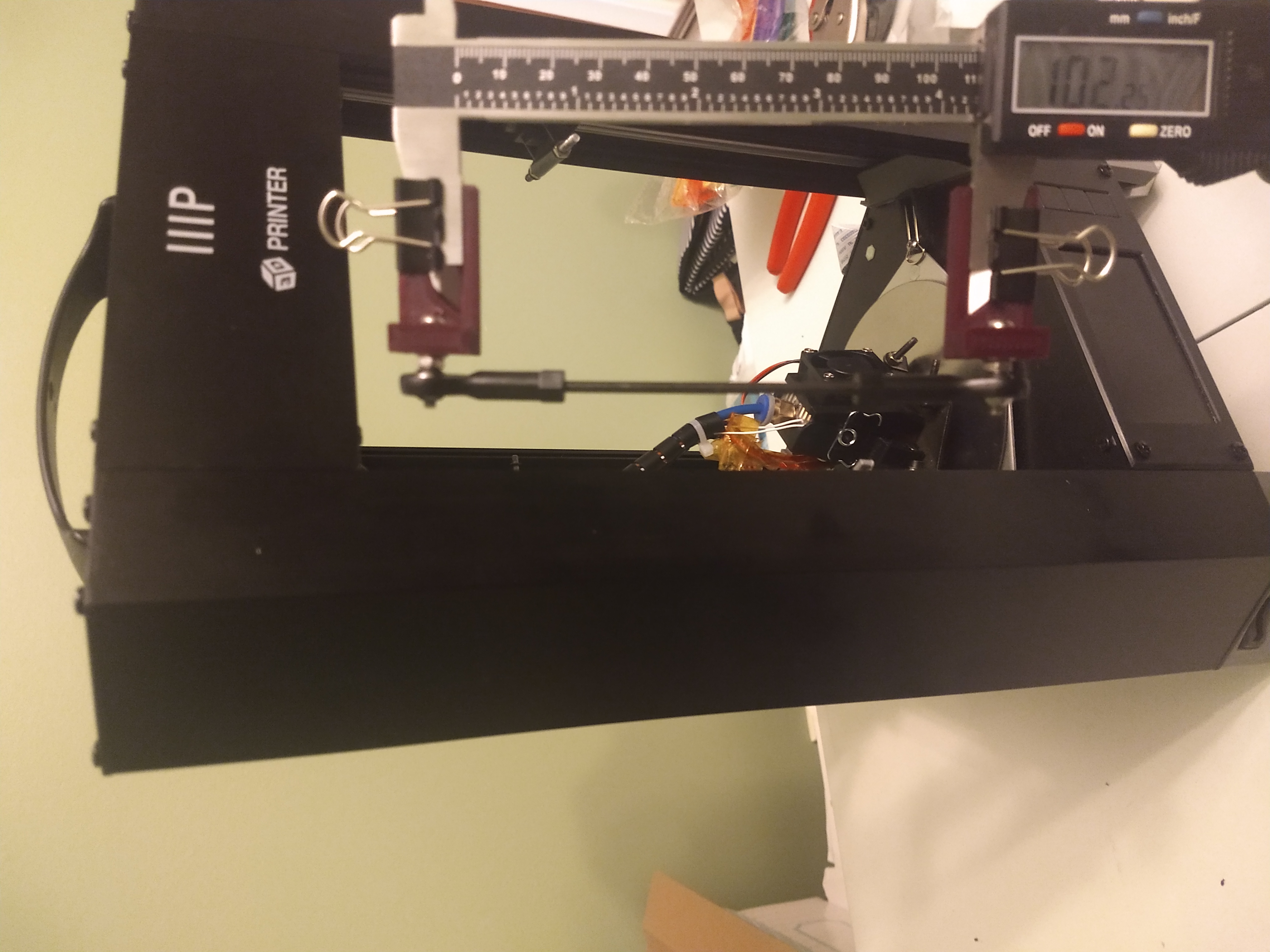
Physically adjusting all arms to be the same length can also help the delta kinematics behave more predictably. If you are trying to achieve perfect dimensional accuracy, this adjustment becomes much more important. It may also positively impact bed leveling. Once again, this is a quality control issue in that some printers may come from the factory better or worse than others. Delta math usually (unless using the advanced offset options) assumes that all arms are the same length.
-
No parts should be broken or malfunctioning. I really should not have to point out the obvious, but I have had people asking about bed leveling issues while neglecting to mention very obvious clicking/grinding/screeching noises. I cannot go to your house, in-person, and point out every possible component that may be broken on your machine. Common culprits are torn/ripped/damaged belts, bad linear bearings, seized arms, stuck/obstructed bed leveling switches, clicky/separated/bad idler pulleys, etc.
Note: Any time you mess with the hardware, you should recalibrate your machine.
The previously mentioned hardware upgrades will help, regardless of the firmware version used. If you're changing firmware versions for the first time, take the time to read through the documentation so that you can understand how the new firmware you flashed behaves differently than the previous firmware version you were using. I may mention some differences on this page, but not all of them (e.g. z-offset is handled in a different way on each of the three firmware versions).
-
Stock Firmware (not recommended) - you are very limited on what you can do with stock firmware. The only new feature versus the P5 tutorial is the addition of the P2 calibration option. Most of the advanced calibration parameters referenced on this page (e.g. M665 ABCDEFXYZ) do not exist on stock firmware. Therefore, if you are on stock firmware, just use the instructions on the P5 tutorial, and if you want to use the P2 calibration pattern, then just use auto_cal_generic.py with those instructions.
-
Marlin4MPMD 1.3.3 by mcheah - This firmware is no longer supported, but the script should also work with it. Note that a few things like the tower rotation flag (explained in the P5 tutorial) and G33 works differently compared to aegean-odyssey's MPMD Marlin 1.1.X.
-
MPMD Marlin 1.1.X by aegean-odyssey - By default, the script will turn off the probe compensation routine (M111 S128) unless you remove that part of the Python code yourself. It also has the option to use a more current version of the G33 routine. Also, for this firmware option, the script's tower flag is used to control the G33 T parameter. (explained more later) .
Many newcomers are puzzled as to why G29 does not solve all bed leveling issues. This is because G29 is only designed to compensate for true uneven/slanted bed issues on a Cartesian machine.
On a delta 3D printer, the math is nonlinear and therefore much more complicated than their cartesian counterparts. The home sensors give your printer its start point, and then it does a bunch of math with the defined M92/M665/M666 parameters to tell the printer how to move and to keep track of where it is currently located. This tracked movement/location is what is reported to the G29 probe readings. The problem, however, is that this math assumes that the machine's hardware is perfectly-aligned. Furthermore, it also assumes that those M92/M665/M666 parameters are perfectly defined. Neither of those, are good assumptions.
Even on cartesian machines, G29 can only compensate so-much for misalignment before it quits working well (e.g., good luck compensating for a bed that is 1 cm lower on one end versus the other). When you add in the extra parameters/complexity/nonlinearity of delta kinematics, then there are even more alignment/calibration parameters you need to address in order for G29 to be able to do its job.
Some may argue that G29 is not needed on a properly calibrated/aligned delta 3D printer. That could be a valid statement for many delta printers, but my experience has been that some sort of bed-leveling mesh is needed on this specific machine to compensate for remaining errors, especially when using a smaller nozzle.
Since this is an advanced tutorial, I will try to briefly cover the delta calibration parameters you can control via the firmware. Now that you have aligned the hardware to the best of your abilities, it is time to adjust the calibration parameters to achieve accurate delta kinematics (printhead movement, bed leveling, dimensional accuracy, etc.). The command-line script argument will be put in parenthesis.
In theory, M666 and M665 define the real-world delta geometrical parameters that help calculate the delta kinematics (i.e. tells the printer how to move). In practice, however, we more-or-less tweak those parameters' numbers iteratively until we find some combination that gives us both dimensional accuracy and a good/level first layer. I.E., just because a parameter may represent some real world measurement/value does not necessarily mean that your final calibrated value will match it. Because of the complexity and nonlinearity of the equations, "everything affects everything" is a safe assumption, which is why it can take an iterative trial-and-error process in order to properly set delta kinematics parameters. Put another way, if you want to fix both bed leveling AND dimensional accuracy, the process gets more complicated.
This is straightforward and already covered in detail on this page. Note that Marlin may default the M92 XYZ 1/16 values to 114.29 instead of 114.28. Feel free to try both to see which one gives you better vertical dimensional accuracy with a test print. Fix M92 first, because it will absolutely affect your other calibration parameters.
Dennis Brown's Note:
114.29 is the correct number. 114.28 was picked as a doubling of the number for x8 (which was rounded down), but the exact fraction has to be taken into account and that takes it up to 114.29. However, belt stretch may be more than this value.
In theory, M666 XYZ is used to adjust the positions of the home sensors (at the top of the printer) via software. It has the most direct impact on bed leveling, but can also affect dimensional accuracy. Adjusting only M666 without also adjusting M665 can sometimes result in a bowl, dome, or dip-shaped movement where the probed height of the center of the bed is significantly different (higher or lower) from the outer edges of the build plate. If this is your first time running the script, you should keep all of the M666 XYZ script input values at 0.0. Non-zero values in these fields can optionally be used later for various trial-and-error solutions.
I do not want to provide a photo of tower locations, because this may vary depending on what hardware and/or firmware tweaks you have performed. You can figure out which tower is which by homing (G28) and then moving the printhead to these positions:
G28 ; Home
G1 X-43.3 Y-25 Z10 ; Tower X
G1 X43.3 Y-25 Z10 ; Tower Y
G1 X0 Y50 Z10 ; Tower Z
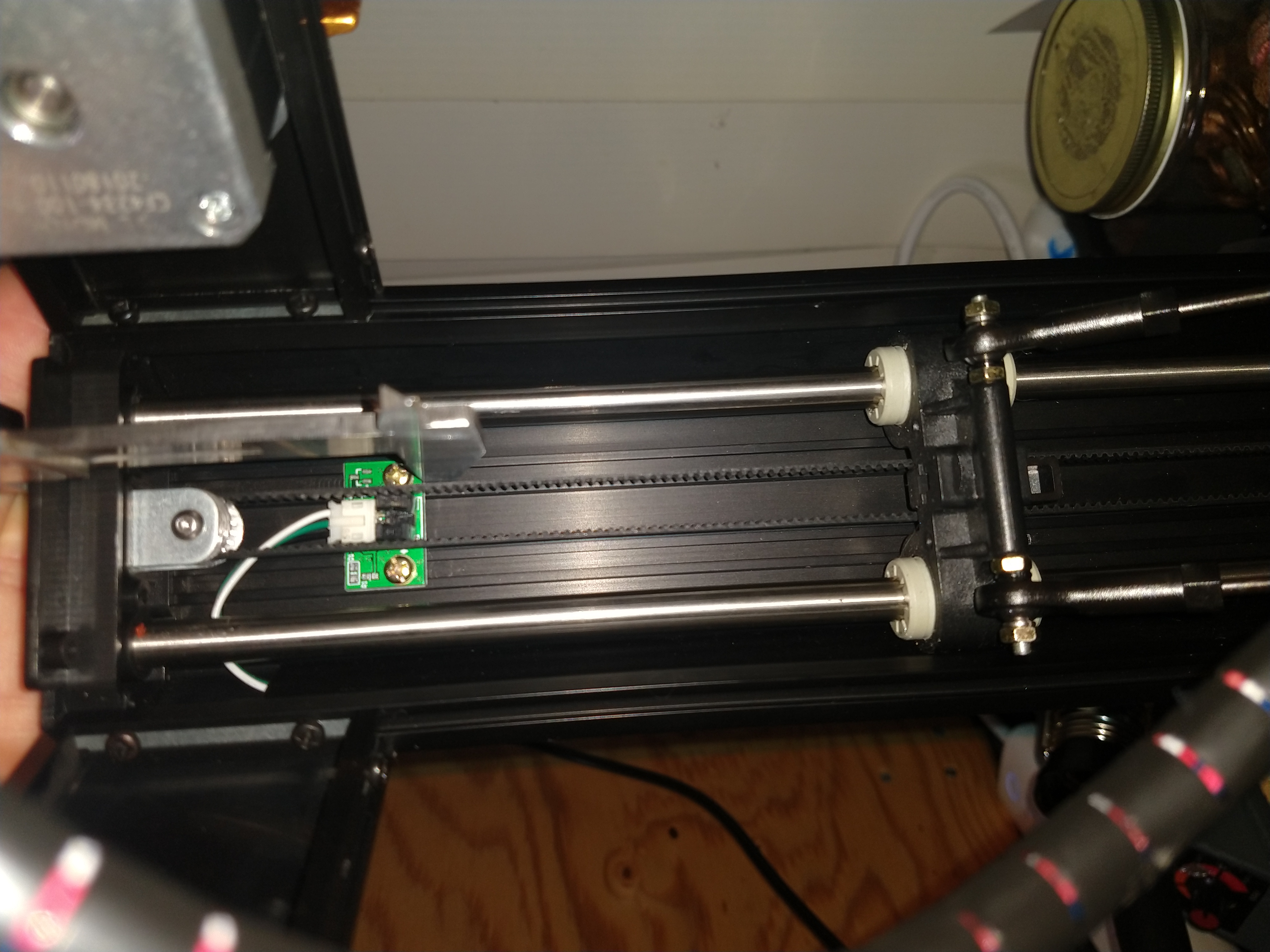
The physical sensors are best adjusted at the factory. They should not be adjusted until it is time for a firmware adjustment to be done with M666. If one of the tower sensors is significantly lower than the others, that sensor can be adjusted higher physically/mechanically to be close to the others. Doing so will give more Z height available by the amount of the adjustment. It is probably not worth doing unless you can gain more than 1 mm. The most likely reason that for one sensor being that far out is because someone other than the factory tried to make a mechanical adjustment (and failed to do it right).
Marlin Reference Page
Visual Representation/Math
These parameters have the most direct impact on dimensional accuracy, but can also affect bed leveling (see M666 notes on the bowl/dome shape). Many other guides (and G33) leave M665 L as a manual-user-entry trial-and-error input whilst using M665 R exclusively to reduce the bowl/dome shape. However, Dennis Brown in the Facebook group derived a simple equation, via experimentation, which can help maintain previously calibrated dimensional accuracy as you continue to adjust M666 XYZ and M665 RL simultaneously.
R_new = R_old - 4.0 * BowlError
L_new = L_old + ratio * (R_new - R_old)
ratio ~ 1.5 for most stock MPMDs, but may vary if your arm lengths are drastically different.
Your starting LR values should ideally come directly from the carbon paper step or basic dimensional accuracy tutorial.
Marlin Reference Page
For all practical purposes, the height is handled when G29 is used to create your bed mesh and/or in your Start Gcode. However, I included this since it appears that the newer G33 routine in later versions of Marlin (not mcheah's version) may be affected somewhat by this when it comes to avoiding "delta calibration error." You are probably okay leaving this at its default value.
Marlin Reference Page
Reddit Discussion
This probably will not affect your calibration results, but I added it to the script so that I would not have to enter it over USB terminal later. It can have a large impact on print quality for certain prints under certain circumstances.
Only applicable to Marlin. Controls the calibration probe radius for most routines in this script. Use this instead of the B parameter mentioned on the Marlin Reference Page. If trying to use G33, you may have to change this for the calibration to succeed. E.G., the firmware's default is 50, but Dennis Brown's testing indicates that 25 mm works the best for the MPMD.
Marlin Reference Page
Marlin4MPMD 1.3.3 Reference Page
G33 in MPMD Marlin 1.1.X has options for automatically adjusting this. Applies an angular offset to the towers. If you edit these values manually, make sure they all add up to 0.00 or some multiple of 360.00.
Dennis Brown's Note:
The manufacturing tolerances and assembly method makes the angles very close to ideal on the MPMD. Don’t expect to see any improvement from adjusting this.
Marlin4MPMD 1.3.3 Reference Page
These are experimental values that were made specifically for Marlin4MPMD and later imported into MPMD Marlin 1.1.X. These are the parameters you will need to adjust to fix dimensional accuracy issues specific to a tower. Zek Negus in the Facebook Group does his final dimensional accuracy tweaks only with the diagonal rod length offsets (ABC); however, I have had luck fixing things just by adjusting the delta radii offsets (DEF). Because of the experimental trial-and-error nature of these adjustments, I would recommend getting M666 XYZ and M665 LR adjusted for the best average dimensional accuracy and bed leveling possible before proceeding here. There is currently no logic in the script for changing/adjusting/calculating M665 ABCDEF automatically. I.E., you will have to choose your own values via trial-and-error.
Dennis Brown's Note:
First find the best average dimensional accuracy with the M665 L/R. Then relative adjustments can be made to M665 DEF (or ABC). One will stay the same. If adjusting another higher, then adjust the last one lower by the same amount to keep the average the same. I have the feeling that adjustments should happen in pairs A/D, B/E, C/F, using the same ratios as L/R to adjust for arm length variations. I have not thoroughly investigated the algorithms for this yet.
This is the serial port the printer is connected to on your computer. This will be the same thing that you see in Pronterface, Octoprint, Repetier, or whatever program you normally use to send commands over USB.
E.G.
Octopi: /dev/ttyACM0
Windows: COM3
Mac: /dev/tty.SOMETHING
You can set the hot end and bed temperature as script arguments so that the firmware will not automatically shut them down while the script is running. I recommend setting the bed temperature to your usual print temperature prior to calibration. A hot end temperature of 100 C can make the carbon paper test come out more clearly. I would not push the hot end temperature too high because oozing filament could adversely impact calibration values and if the bed material is something other than bare glass or metal, the hot nozzle may damage the printing surface.
0 = Stock Firmware
1 = Marlin4MPMD 1.2.2 or 1.3.3
2 = MPMD Marlin 1.1.X
Stock Firmware = 0
Marlin4MPMD 1.3.3: Probably 1, but read the discussion in the P5 tutorial. If you did the motor swap to make parts face forward in the stock FW, but changed to Marlin4MPMD, it will be less confusing to undo that change, as this FW makes the standard wiring face forward.
MPMD Marlin 1.1.X: Experimental G33 T option - 0 (do not rotate towers) or 1 (rotate towers M665 XYZ).
This method/pattern refers to the script's logic/routine for calibrating M665/M666 automatically. These could correspond to existing G29 patterns, existing G33 patterns, and/or custom emulated patterns. For example, G29 P5 does not exist in Marlin4MPMD, but if selected, the script will emulate that probe pattern for endstop calibration, regardless of the firmware version.
I have experimented with several methods/patterns, some with more success than others. For simplicity, I will only emphasize the few that I believe may work best in common situations.
5: Stock or Marlin4MPMD or MPMD Marlin 1.1.X - G29 P5 pattern. Same as the auto_cal_p5_v0.py script.
2: Stock or Marlin4MPMD or MPMD Marlin 1.1.X - 1 center point, 3 tower points, probe radius determined by -vvv input parameter.
Experimental Patterns (some not listed):
332-340: MPMD Marlin 1.1.X Only - Uses Built-In G33 with automatic M665 L adjustment added.
Last digit is for G33_P parameter (e.g. 334 = G33 P4).
https://marlinfw.org/docs/gcode/G033.html
Which pattern should you use?
Stock Firmware
5 works best with a properly setup bed. Follow ALL of the instructions in the P5 tutorial.
2 might work better if you still have the stock sticker or you skipped other steps. Note that, only for stock firmware, option 2 always uses the G29 P2 50 mm probe radius. No promises. Do not whine if it does not work well for you.
Marlin4MPMD 1.3.3
Option 2 with a 25 mm probe radius (-vvv) worked best on my machine. Dennis's tests also suggest that a 25 mm calibration radius is superior.
aegean-odyssey's MPMD Marlin 1.1.X
I am still doing ongoing experimentation here.
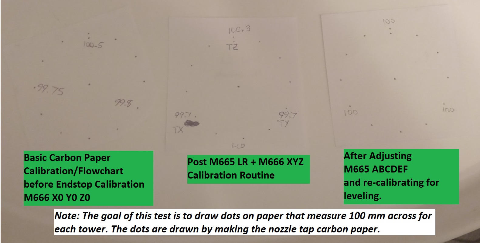
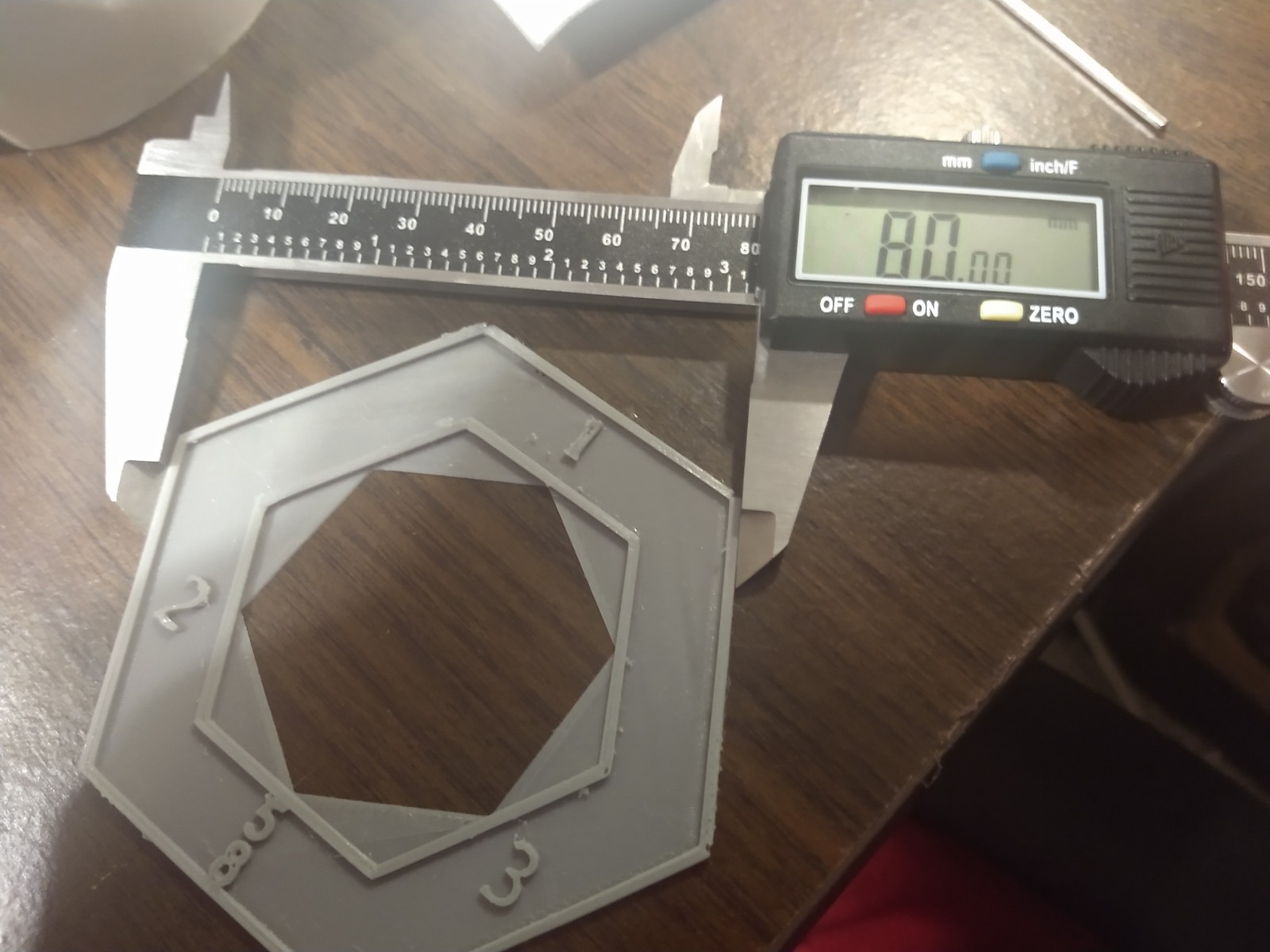
This script adds a prompt after completion asking whether or not you want to run the carbon paper test for dimensional accuracy. This is covered in both the Calibration Roadmap and this video. In the context of the previous two links, it is part of a flow chart used to calibrate dimensional accuracy prior to running the script. For this advanced tutorial, if you care about dimensional accuracy, it is assumed that you have already done this. Because of how the script's math works, you really want the average as close to 100 mm as feasible so that your final M665 ABCDEF tweaks will not have as large of an effect on bed leveling.
So why add prompts to run it after the script has completed? Because as we dive deeper into the weeds, we may need to manually adjust M665 ABCDEF for dimensional accuracy, re-level the bed, and then check dimensional accuracy again. This could lead to a need to re-draw the dots many times.
You could also do a test print for dimensional accuracy, such as this one. However, keep in mind that over/under-extrusion (covered in this tutorial) may affect your results when actually printing objects. Meanwhile, the carbon paper test tells the nozzle to move to a set of X/Y coordinates and probe the plate - no extrusion involved!
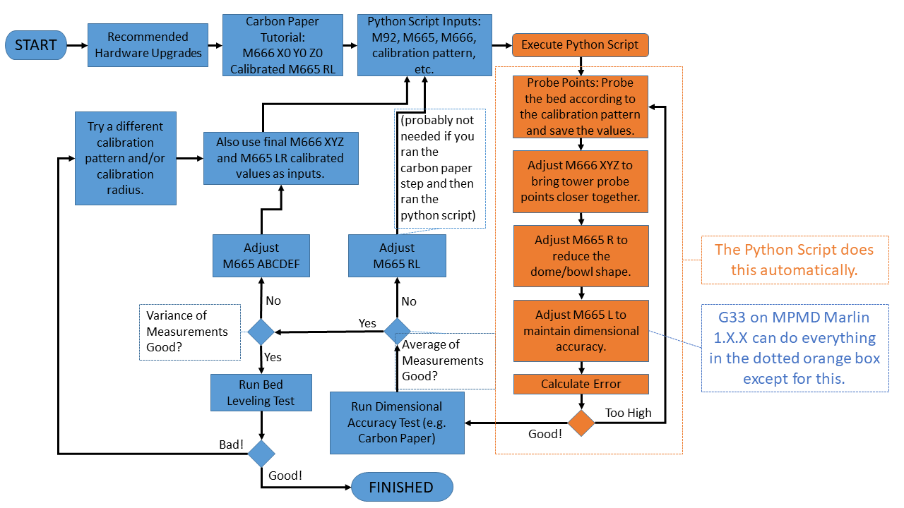
The items in orange are handled automatically by the Python script. The other items require some amount of user input/interaction, but might be made more convenient by the script (e.g. prompts for running the carbon paper test and/or G29 as well as logging data). When I first started working on this script, G33 was not nearly as robust. As it stands now, you may choose to do the calibration without the Python script. I left enough information in the flowchart to allow you to make your own decision.
If you followed the instructions for running the carbon paper test and then used those as inputs into the Python script, then you probably should not need to do this. Otherwise, if you are using the script and you do not have good average dimensional accuracy at the end of the runs, then I would recommend revisiting the carbon paper step for adjusting only M665 R and then starting over with the whole calibration (M666 X0 Y0 Z0). I.E., you could just re-run the script and only change M665 R as an input.
Because of the equations used, it is best to get everything as close as possible (average, not over/under-shooting) prior to adjusting these. The idea is to try different values here as script inputs until you get good dimensional accuracy test results.
For me, I found that I was able to get good results by only adjusting M665 DEF, which relates to M665 R. The M665 DEF values were all very close to +/- 0.3 because of previous alignment/calibration work that I did. The same rule of thumb applies here as in the carbon paper tutorial for M665 R. I.E. ~0.1 mm change in dimensional accuracy corresponds to about ~0.1 mm change in M665 DEF.
Zek Negus in the Facebook Group has achieved good results by adjusting M665 ABC. Note that he does not use my Python script and instead opts to use the Marlin4MPMD 1.3.3 flavor of G33. The M665 ABC parameters are related to the M665 L parameter. The general rule of thumb is that if your print is coming out too large, you should increase the rod length, and if the print is coming it too small, you should decrease the rod length.
Once again, more details on these parameters are in the Marlin4MPMD Calibration Wiki.
Before printing, you will need to make sure that you have created a fresh G29 mesh (the script will prompt you to do this) and that you have saved everything with M500.
You can look at a heat map (see the downloadable spreadsheet) if you have done all of the recommended hardware alignments, but the final test is done by actually printing. Make sure to read the next section on "Final Bed Leveling Tweaks" before getting fed up with calibration.
Comprehensive Ring Test Print
Less Comprehensive Low Filament Usage Calibrator
Note that the ring test may have to be slightly resized because apparently Cura does not like objects that are exactly 110 mm on a 110 mm diameter plate. I was able to do 108 mm without a skirt. I also recommend changing the height of whichever print you choose to match your Initial Layer Height. That way, you will have a clear idea of where any leveling issues might lie. Dennis Brown was able to print closer to a 110 mm diameter by increasing the size of the print bed in Cura to 111 mm.

If you have performed all of the recommended hardware alignments, calibrated your machine properly, and you are using a 0.4 mm nozzle, then you should not need anything else beyond a few adhesion and slicer settings changes (covered in the first point here). However, if you're not using a perfectly flat surface, using a 0.2 mm nozzle, or you did not do all of the previously mentioned recommendations, then you may have to do some additional work. It is also important to note that the bed probe readings (and therefore also the heat map) only makes sense if you have performed all of the recommended hardware upgrades/alignments/calibrations.
-
Look for "FAQ: Bed Adhesion and First Layer Help!" in the table of contents of the Calibration Roadmap. I am not going to repeat everything here. These should be your first courses of action. If you have done everything that you were supposed to do, then this should be enough with a 0.4 mm nozzle.
-
Try using a different calibration pattern for the script input (-patt). This script is highly experimental, so I cannot always tell you which calibration pattern may work better/worse for you.
-
You may need to make a few eyeball tweaks to your final M666 XYZ values to make the first layer a bit flatter. Dennis's Note: Probably only needed if you performed the M666 alignment at a radius >25mm.
-
My second MPMD has a WhamBam Flexplate installed directly to the stock surface. I temporarily removed the flexplate, set a $2 five-inch craft mirror on top of the magnet (using a thermal pad), and then calibrated M665/M666. I swapped the mirror back out for the FlexPlate when performing G29. This immediately yielded better test print results versus trying a bunch of calibration patterns on the non-flat surface. Dennis's Note: I stuck my magnet to a glass plate first, so my results are excellent with my removable steel plate.
-
aegean-odyssey's MPMD Marlin 1.1.X has additional post-processing options. After running G29, also running G29 C1 can fit a least-squares fit plane to the bed mesh. G29 C1 probably works better with a glass plate. For a non-flat surface, one of his experimental bed mesh post-processing scripts may work better for you.
-
Both Marlin4MPMD and MPMD Marlin 1.1.X have the ability to manually edit your bed mesh. The Marlin4MPMD Calibration Wiki Page has detailed instructions for that version of firmware. I am currently doing experimentation with the spreadsheet on this project to manually edit points in aegean-odyssey's MPMD Marlin 1.1.X. There is additional experimental discussion in this post.
Much like the P5 tutorial, you will need to create your G29 mesh (Marlin) and save your ending values to EEPROM via M500 (Marlin only) or save them to your Start Gcode.